The action of selection of a cross-section for a structural member is common for most working modes of the application. To avoid unnecessary repetitions, these operations are described here separately.
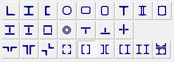
The application works with various types of cross-section shown in the figure below.

They include rolled and roll-formed profiles (rectangular pipes are considered in two possible orientations, horizontal and vertical), three types of sections welded from sheets/plates, and built-up sections from rolled profiles. Moreover, the Resistance of Sections mode enables to check (for strength) any section created in Section Builder, Consul, or Tonus. It should be noted that when a section created by Section Builder or Tonus is recognized as a standard section for Kristall (welded I-section, welded hollow section or double angles), an application generates a respective message and treats this section as a standard one.
If the section is a rolled or roll-formed profile, or if it contains one, it can be selected from a tree-like profile database. First level of the tree is used to choose a catalogue of rolled profiles from which to select the desired section. It contains only the catalogues included in the In Use list.
Second level enables you to select a group of rolled profiles of one type (such as I-beams, channels, angles, etc.). The list of accessible profile groups is defined by the selected cross-section type. For example, if you have selected the first section type, only the Equal Angles and Unequal Angles will be accessible.
Third level enables to select a particular profile which will be used in the cross-section of the member.
If you have selected a single angle section, you can also specify the type of the structural member in the drop-down list.
You can choose from the following types:
Based on the selected type, software will automatically perform the stability analysis in the principal axes or structural axes according to the requirements of the selected design codes.
Clicking the button  invokes the dialog box which provides the standard values of the effective
lengths and limit slenderness recommended by the codes. Clicking the Apply
button will transfer this information to the calculation parameters.
The type of the connecting lattice for a built-up section with chords connected by lattices can be selected using the respective buttons. Once it is selected, a table appears which includes buttons for selecting sections of the lattice members and text fields for specifying properties of the lattice.
The limitations imposed on the properties of the lattices are listed in tables.
Built-up (welded) cross-sections defined in the application can be saved
in a custom user database. This can be done by clicking the Save
cross-section in the user database button —  .
.
Custom sections dialog box will appear where you can specify a name for the section you want to save. Since the application does not verify the uniqueness of the names used, it is the user who has to take care of it.
To access the sections from the user database click the Load
cross-section from the user database button —  .
The list of sections is displayed in the Custom
sections dialog box.
If duplicate names are detected in the database, use the Rename button to change the name of the respective profile.
Any of the sections listed in the Custom sections dialog box can be selected for further work. To do this, highlight the respective row in the table and exit the dialog by clicking the Apply button.
Properties of the selected section can be browsed in the Section Properties dialog box which is invoked by the Geometric Properties button. The section is displayed to scale, principal axes of inertia and main sizes are indicated.
The geometric properties are calculated by the application with certain accuracy. Therefore some of them may be slightly different from the reference data given in catalogues.
If the section includes rolled profiles, the catalogues containing data on these profiles must be included in the In use list.
The application performs an automatic check of the section design. The
list of limitations is given in tables. When
some of the limitations are violated, an error message with the description
of the error will appear. Moreover, clicking the button  in the respective
dialog boxes will display the sizes limitations.
In some cases the application allows you to ignore the warning that some limitations are violated (Ignore button). However, the negative consequences of this decision will not be analyzed.
In cases when an invalid numerical value is specified for a parameter, the error message will say Invalid data. Such a check is performed in all working modes.