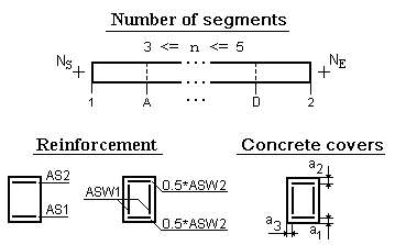
This dialog box is used to specify the information on beam reinforcement, which is required for designing. This information includes the data on the areas of the upper and lower longitudinal, as well as transverse reinforcement, class and standards of the reinforcement, and the value of the concrete cover.
Beams are divided into two types: Main and Secondary. All nodes of a secondary beam can be supporting. A beam can be connected to a column, a wall or another beam by these nodes. If a beam supports other beams, it is considered to be the main beam, and some of its nodes may be non-supporting ones. For example, those can be the nodes the secondary beams rest on.
The beam type is specified using the radio buttons. The lists of all nodes the given beam passes through are displayed in the Beam nodes and Extreme and support beam nodes text fields. It is necessary to correct the list in the second field (Extreme and support beam nodes), removing the numbers of non-supporting nodes from it. This means that the reinforcement area in a beam is specified only in the segments between the supporting nodes.
Data on the reinforcement areas are entered in the table that contains information only on one beam. The information is divided into sections according to the number of spans between the supporting nodes of the beam. Span is a part of a beam between the supporting nodes or between one supporting node and the extreme unfixed node (in case of a cantilever). The reinforcement area is specified for the given number of segments between the supporting nodes of the span (this value is entered in the respective text field), and in the case of an unfixed node – between this unfixed node and the supporting node.

Once you have specified the beam type, the number of segments between supporting nodes, and the list of supporting nodes, click the Apply button. Then the number and length of segments in the table will be corrected in accordance with the specified number of spans and segments.
The first three columns of the table are filled automatically and include the following data:
the first column — numbers of the nodes at the beginning and in the end of the span (Ns and Ne, respectively);
the second and third columns — identifiers of the segment in the span (Nsi, Nei), for example if the beam span between the nodes 33 and 34 is divided into three segments, the segments will have the following designations: 33-A, A-B, B-34;
the fourth column — the area of the lower longitudinal reinforcement in the segment — AS1 (cm2);
the fifth column — the area of the upper longitudinal reinforcement in the segment — AS2 (cm2);
the sixth column — the area of the vertical transverse reinforcement in the segment — ASW1 (cm2/m) ;
the seventh column — the area of the horizontal transverse reinforcement in the segment — ASW2 (cm2/m). It is specified if the action of shear force on the beam has to be taken into account. If this column is blank, structural reinforcement connecting the cages is installed.
It is recommended to stick to the following order of data preparation on this dialog box:
Once the table is filled select the next beam in the list and repeat the above steps.
In those cases when the characteristics of beam reinforcement can be taken either entirely or partially from the characteristics specified earlier for another beam, you can use the Copy button. The number (name) of the beam the reinforcement characteristics of which you want to copy for the current beam is selected in the Copy dialog box.
The rules for specifying the beam reinforcement are given in the information window, which can be invoked by clicking the  button.
In the Reinforcement group of the dialog box you can specify whether the beam is reinforced by welded cages or by individual bars (without bends).
It should be noted that the Beam name list will include only original names, i.e. there will be no repetitions of identical names. If there are unified groups of beams in the project, the list will contain only the name of the first beam of the group with a list of its corresponding nodes.
The drawings with the results of the design are generated only for the first beam of each group. All other project materials (Cages, Steel consumption Sheet, Overall specification) will include the information on all beams of the respective groups.
If the beam reinforcement was selected with the account of torsion, you have to check the Torsion checkbox. In this case, the respective recommendations both for the tied reinforcement and welded cages will be taken into account in the designing process.
If there is a possibility of fire action on the floor, beams are provided with additional reinforcement in the form of a reinforcing mesh for the installation of which it is necessary to check the Presence of additional mesh checkbox.
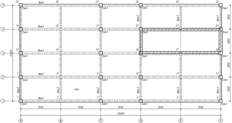
The floor structural layout is given in the figure, where the Bm1 beam is assigned the Main type. The beam is connected to the Cm1 columns in nodes 1, 3, 4 and 6, which are considered to be the supporting nodes. The secondary beams Bm4 and Bm5 bear on the Bm1 beam in nodes 2 and 5.
When preparing the data in the Beam Reinforcement dialog box, after selecting the Bm1 beam and specifying its type (Main), it is necessary to correct the list of supporting nodes in the Beam name list by removing the nodes 2 and 5 from it. This done, you have to click the Apply button, after which the reinforcement table will display three segments: 1-3, 3-4 and 4-6, where the reinforcement area values are specified. Similar operations have to be performed to describe the Bm3 main beam, in which case the node 14 has to be removed from the list of supporting nodes of this beam.

Structural layout of the floor