Rigid Bodies
One of the possible types of poly-constraints is the case when the displacements of some nodes of the system are connected to each other as in the case of their connection by a rigid body. In the SCAD software the rigid body is treated as a specific type of finite element. Its relationship to finite elements can be noticed at least from the fact that the rigid body unites nodes attached to it. Roughly, a rigid body can be considered as a limiting case of a finite element as the rigidity properties of this element approach the infinity.
Rigid body can be represented graphically as a "spider" consisting of one master node and a number of slave nodes – Fig. 1 The connection can be full or partial.
|
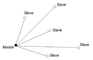
Figure 1
|
We have to distinguish between linear and angular components of the vector of nodal displacements Z. The first ones will be denoted as u, and the second ones as θ.
When the connection is full all the displacements of the slave nodes are expressed through the displacements of the master node on the basis of the kinematics theorems for a rigid body:
|
\[ \left( {{\begin{array}{*{20}c} {{\rm {\bf u}}_{S} } \\ {{\rm {\bf \theta }}_{S} } \\ \end{array} }} \right)=\left( {{\begin{array}{*{20}c} {{\rm {\bf u}}_{M} +{\rm {\bf \theta }}_{M} \times {\rm {\bf \rho }}_{M-S} } \\ {{\rm {\bf \theta }}_{M} } \\ \end{array} }} \right), \]
|
(11)
|
|
where u, θ are vectors of linear displacements and angles of rotation of the node in the global coordinate system, and the indices M and S stand for the master and slave nodes respectively;
ρM-S is the radius vector connecting the master node to the slave one.
In the case of partial connection the expression (11) covers only those degrees of freedom which satisfy the kinematic relationships of a rigid body. Other displacements and angles of rotation of each of the slave nodes remain independent and are not expressed through the displacements of the master node. Such connection can be represented as a connection in two stages. The full connection of displacements and rotation angles of all slave nodes with displacements and angles of rotation of the master node is performed during the first stage, and then independent degrees of freedom of the slave nodes are disconnected.
Since the equations (11) include the angle of rotation of the master-node, when using the rigid bodies only the design models with the degrees of freedom including the angles of rotation (type 2, type 3 and type 5) can be used. If there are no angles of rotation in other nodes due to the selection of the respective types of finite elements, it is recommended to impose the missing constraints.
The connection codes are introduced for the convenience of specifying the connection types. The connection codes for the spatial design model are as follows X, Y, Z, UX, UY, UZ.
Each of these parameters is set to f or b. The value b (blocked) means that the connection of displacements corresponding to the given degree of freedom (in the global coordinate system) is performed, and the value f (free) means that it is not performed.
There are the following possible options of a set of nodal displacements in the connection code:
- spatial design model – connection codes X, Y, Z, UX, UY, UZ;
- two-dimensional frame – connection codes X, Z, UY (this type of a rigid body imposes displacements on the slave nodes in its own plane, such a rigid body can be called a disc);
- bendable plate located in the XOY plane – connection codes Z, UX, UY (this type of a rigid body, which can be called a stamp, connects the displacements of the nodes belonging to it at their exit from the plane of the rigid body).
It should be noted that, on the one hand, the rigid bodies (and all the poly-constraints) are an extremely powerful tool for creating the design models, which enables the user to express their individual creativity in the most unusual situations. On the other hand, this tool is not safe – even the experienced designers can get into a well hidden trap, which is difficult to detect. One of such traps is the condition of linear independence. This means that the design model should not contain a statically indeterminate subsystem consisting entirely of rigid elements. Otherwise, the distribution of forces in the system is not unique.
Let us consider some typical examples of using the rigid bodies. Figure 2,a shows the structure of a strong slab reinforced by wide ribs. Application of the traditional approaches for modeling this structure with the help of rigid inserts will make the bending of the slab in the span between the reinforcing ribs considerably greater than in the case when the reduction of the slab span due to the rib width is taken into account.
Using the rigid bodies in the model (they are limited by the dashed line in the figure) enables to join the bar with the necessary eccentricity to the nodes on the middle surface of the plate, and to provide the absence of distortion of the section at the junction with the plate, which prevents its bending in this area. It should be noted that in this case the spatial rigid body can be used, despite the fact that all its nodes are in the same plane.
The absence of distortion of the cross-section contour in the models made from the thin-walled bars is often provided by the introduction of diaphragms or similar stiffening elements. If these elements are not loaded and their stress state is of no importance to the designer, the diaphragms can be modeled by rigid bodies which do not allow deformations in their plane.
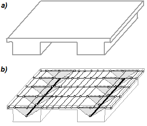
Figure 2. Modeling of a wide rib by the rigid bodies
An example connection of plates of different thicknesses with one of the surfaces aligned is shown in the Figure 3. It is advisable to use a rigid body with pairs of nodes along the line of thickness variation adjacent to different middle surfaces of the plates.
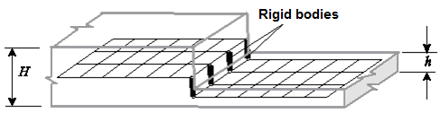
Figure 3. Modeling of a non-central thickness jump
It should be noted that simply merging the displacements of the upper and lower nodes will not provide an adequate description of the performance features of such a connection since the tangential displacement of the upper node is determined not only by the tangential displacement of the lower node, but also by its angle of rotation.
This approach can be also applied in the case when the step between the upper and lower plates is formed by the beam (see Fig. 4). Three-node rigid bodies with a bar element modeling a beam attached to their middle node are used here.
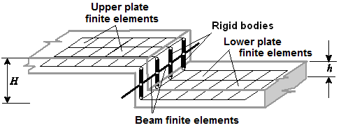
Figure 4. Modeling of a step
Returning to the connection of plates of different thicknesses with one of the surfaces aligned, it should be noted that when the rigid bodies are used, the nodes of the parts of the plate with different thicknesses are located at different levels, which may not always be convenient. You can place all nodes at the same level and use the “Move the plate midplane” option, which will also lead to the desired effect.
A typical example of the application of the rigid bodies is modeling of the joint area of monolithic columns and floor slabs (see Fig. 5). Dimensions of a rigid body in this case correspond to the dimensions of the column cross-section. It should be noted that the rigid bodies can be automatically entered into the joint area in the FORUM preprocessor.
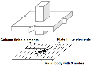
Figure 5. Modeling of the slab-to-column joint area