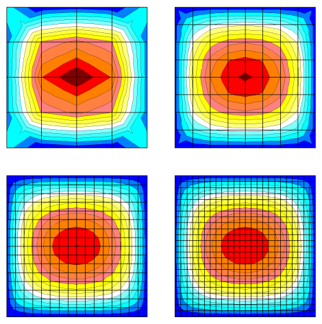
Below, a comparative analysis of a simply supported square plate, loaded by a uniformly distributed load throughout its area, is given. The analyses were performed with four finite element meshes: 4×4, 8×8, 16×16 and 24×24 (Fig. 1).
Figure 1. Isofields of bending moments obtained with different design models and finite element meshes
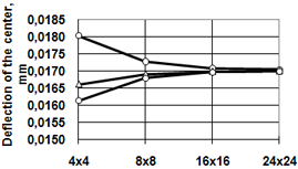
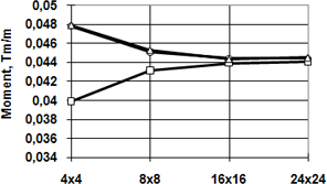
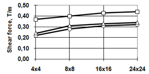
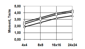
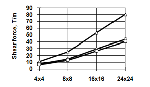
Table 1 contains results regarding displacements, bending moments, and shear forces obtained for the finite elements of different types on the aforesaid meshes. The same data are shown as plots in Fig. 2.
As one can see in Table 1 and Fig. 2, the practical convergence takes place for the deflections and bending moments with the use of finite elements of different types. For the shear forces, elements of the 11th type give values noticeably different from those obtained by the use of other finite elements. It should be noted that the element of the 20/50 type was connected to four nodes only, though it was possible to introduce more nodes on its sides (up to 8 nodes in total).
Checkup calculations of this system showed that the accuracy of the results improved significantly and became close to that obtained with meshes twice as dense. For example, for a mesh of 8×8 elements the deflection was 0.01701, the bending moment was 0.0442, and the shear force was 0.278.Table 1
|
Displacements of the plate center for the mesh |
|||
|---|---|---|---|---|
FE type |
4x4 |
8x8 |
16x16 |
24x24 |
11/41 |
0,0180329 |
0,0172754 |
0,0170823 |
0,0170453 |
20/50 |
0,0166168 |
0,0169137 |
0,0169918 |
0,0170051 |
12/42 |
0,0161403 |
0,0168034 |
0,0169658 |
0,0169938 |
|
Moment at the center of the plate |
|||
М -11/41 |
0,04781 |
0,04509 |
0,04443 |
0,04443 |
М -20/50 |
0,03991 |
0,04313 |
0,04393 |
0,04408 |
М -12/42 |
0,04787 |
0,04528 |
0,04432 |
0,04448 |
|
Shear force at the edge |
|||
Q -11/41 |
0,22 |
0,28 |
0,31 |
0,32 |
Q -20/50 |
0,37 |
0,4 |
0,43 |
0,44 |
Q -12/42 |
0,24 |
0,31 |
0,33 |
0,34 |
а)
|
b)
|
c)
|
Legend:
Figure 2. The convergence of results for a distributed loading: (а) by deflections; (b) by moments; (c) by shear forces |
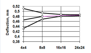
In another series of numerical experiments, when the same plate was loaded by a concentrated force, results shown in Table 2 and in Fig. 3 prove to be less optimistic. Here the practical convergence rate of the moments slows down, and that of the shear forces does even more significantly. The values of the latter were taken in a point located at a quarter of the plate thickness from its center. Apparently, values of the shear forces in points so close to the location of the concentrated force should not be taken into consideration at all. This issue is discussed in more detail in sections that follow.
Table 2
|
Displacements of the plate center for the mesh |
||||
|---|---|---|---|---|---|
FE type |
4x4 |
8x8 |
16x16 |
24x24 |
|
11/41 |
0.511522 |
0.494164 |
0.488470 |
0.487183 |
|
20/50 |
0.466266 |
0.480460 |
0.484425 |
0.485222 |
|
12/42 |
0.432918 |
0.470046 |
0.481375 |
0.483493 |
|
|
Moment at the center of the plate |
||||
М -11/41 |
2.61566 |
3.27276 |
3.93364 |
4.32066 |
|
М -20/50 |
2.31761 |
3.04494 |
3.72290 |
4.11309 |
|
М -12/42 |
1.89259 |
2.52465 |
3.17713 |
3.56252 |
|
|
Shear force near the center |
||||
Q -11/41 |
7.26 |
14.58 |
29.18 |
43.77 |
|
Q -20/50 |
6.50 |
13.31 |
26.81 |
40.26 |
|
Q -12/42 |
11.37 |
25.59 |
53.21 |
80.42 |
|
a)
|
b)
|
c)
|
Legend:
Figure 3. The convergence of results for a concentrated force: (а) by deflections, (b) by moments, (c) by shear forces |
It should be noted that the quicker convergence of results for some finite element types is paid for by a noticeably longer computation time. Therefore, the loss of time caused by the use of those elements and the computation time spent for the solution of the same problem on a finer mesh with elements of another type should be compared.