a)
|
b)
|
c)
|
d)
|
e)
|
f)
|
g)
|
Figure 1. Slabs a,
b, c, d, e, f, g t — crack on the
lower surface; |
Following [3], first of all consider the conditions of the possible formation of cracks in the slab, which indicate the need for reinforcement. The analysis is performed on an example of studying the behavior of some small in plan characteristic elements with cracks extracted from the structure. Since there are no fundamental differences between the performance of a small element of the slab and that of the shell (the curvature of the shell has no effect within the small area), we will consider flat plates taking both bending and membrane groups of forces, i.e. the combined action of all three moments (bending and torque) and three forces (normal and shear) on the elements is considered.
a)
|
b)
|
c)
|
d)
|
e)
|
f)
|
g)
|
Figure 1. Slabs a,
b, c, d, e, f, g t — crack on the
lower surface; |
The considered elements are assumed to be such that we can neglect the effect of shear forces on their deformability and strength both before and after the appearance of cracks. Due to this hypothesis the considered slabs belong to the category of thin slabs. If it has been somehow established that it is possible to neglect the action of shear forces, the obtained conclusions can be applied to plates of medium thickness as well.
The character of deformation of reinforced concrete spatial structures in areas with cracks depends on the arrangement of cracks, i.e. orientation of cracks with respect to the directions of reinforcement, mutual intersection of cracks, formation of cracks on one or both surfaces of the element, whether the cracks are through or non-through. Through cracks occur in a membrane stress state (in elements in the plane stress-strain state such as deep beams) or under the additional action of small moments. It is assumed that cracks are normal to the middle surface of elements.
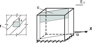
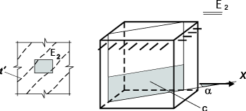
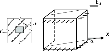
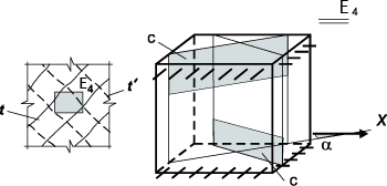
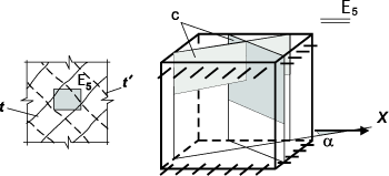
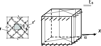
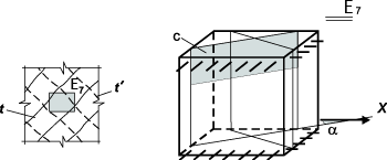
The variety of cracks in elements can be reduced to seven arrangements (Fig. 1):
All arrangements can be divided in two large groups: group N — nonintersecting cracks (see Fig. 1) (arrangements a, b, c), and group I — intersecting cracks (arrangements d, e, f, g).
Conditions of crack formation for elements subjected to the combined action of moments and normal forces can be formulated as a generalization of the theory of core moments of the crack formation of bar systems. The suggestion comes down to applying the theory of core moments of Gvozdev A.A. and Dmitriev S.A. [1] to more complex concrete structures of slabs and shells.
Two surfaces in the element at the distance of ± rя from the middle surface are called the upper and lower surfaces of core points respectively. The value rя= h/6 is determined as for a strip of slab by the formula of the strength of materials.
Let’s introduce two new tensors of core moments: оne with component Мсх, Мсу and Мсху, where
Мсх = Мх + Nх rс; Мсу = My + Ny rс; Мсхy = Мхy + Nxy rс , |
(1) |
and the other with components
М'сх = - Мх + Nх rс; М'су = - My + Ny rс; М'схy = - Мхy + Nxy rс . |
(2) |
From the very definition of core sizes which are calculated based on the condition of zero stresses on the edge of a cross-section [3], it follows that the appearance of the positive core moment means that there is tension on the respective edge. If we assume that tension has to be taken by reinforcement, the decision on whether the reinforcement is necessary is made based on the analysis of the following inequalities:
for the lower area of the element:
Мс.max ≤ 0; Мc.min ≤ 0, |
(3) |
for the upper area of the element:
М'c.max ≤ 0; М'c.min ≤ 0. |
(4) |
If the first condition is violated (3), a crack is formed according to the arrangement α (Fig. 1) on the area subjected to the main core moment Мс.max. The angle α between this area (crack) and the Х axis at the moment of violation of the first inequality (3) can be determined using the following expression
tgα = (Мс.max – Мсy)/ Мсxy. |
(5) |
When the first inequality is violated (4), the cracks are formed according to the arrangement b (Fig. 1). The angle between the upper crack and the Х axis can be determined using the following expression
tga = (М'c.max - М'cy)/ М'cxy. |
(6) |
Simultaneous violation of the first condition (3) or the first condition (4) and of the additional inequality Ncl≤ 0,75Rph indicates that cracks are formed according to the arrangement c (Fig. 1). Additional inequality is established on the basis of the assumption that the through cracks are formed at the moment when the cross section has an unambiguous trapezoidal diagram of tensile normal stresses equal on one of the extreme and middle surface to Rp, and on the other extreme surface —to zero.
Simultaneous violation of the first inequality (3) and of the first inequality (4) indicates that cracks are formed according to the arrangement d (Fig. 1).
Violation of two inequalities (3) indicates that cracks are formed in the lower area according to the arrangement e (Fig. 1), and violation of two inequalities (4) indicates that cracks are formed in the upper area according to the arrangement e.
It is assumed that simultaneous violation of conditions (3) and of inequalities Ncl≤ 0,75Rph and Nc2 ≤ 0,75Rph or (4) and inequalities N'cl≤ 0,75Rph and N'c2 ≤ 0,75Rph leads to the formation of cracks according to the arrangement f (Fig. 1).
Here Ncl, Nc2, N'cl, N'c2 are the values of normal stresses on the respective areas subjected to the core moments.
Simultaneous violation of the condition (3) and of only one of the inequalities Ncl≤ 0,75Rph and Nc2 ≤ 0,75Rph or of the conditions (4) and of only one of the inequalities N'cl≤ 0,75Rph and N'c2≤ 0,75Rph indicates that cracks are formed according to the arrangement g (Fig. 1).