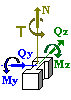
Analysis of a Reinforced Concrete Foundation Slab for Normal Crack Opening

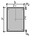
Figure 1. Design cross-section of the element
Objective: Check the calculation of the crack opening width.
Task: Verify the correctness of the analysis of normal crack opening.
References:
1. Guide on designing of concrete and reinforced concrete structures made of heavy-weight concrete (no prestressing) (to SP 52-101-2003), 2005, p. 155-157.
2. M.A. Perelmuter, K.V. Popok, L.N. Skoruk, Calculation of the Normal Crack Opening Width for SP 63.13330.2012, Concrete and Reinforced Concrete, 2014, №1, p.21,22
Initial data file:
Example 43.SAV
report – Arbat 43.doc
Compliance with the codes: SP 52-101-2003, SP 63.13330.2012.
Initial data:
| b×h = 1150×300 mm | Slab section sizes |
| а = 42 mm | Distance from the center of gravity of the reinforcement to he compressed edge of the section |
| As = 923 mm2 (6Ø14) | Cross-sectional area of reinforcement |
| Ml = 50 kH∙m | Moment in the design section from permanent and long-term loads |
| Msh = 10 kH∙m | Moment from short-term loads |
|
Concrete class |
В15 А400 |
ARBAT initial data:
Importance factor γn = 1
Importance factor (serviceability limit state) = 1
Member length 1 m
Effective length factor in the XoY plane 1
Effective length factor in the XoZ plane 1
Random eccentricity along Z according to SNiP 52-01-2003 (Russia)
Random eccentricity along Y according to SNiP 52-01-2003 (Russia)
Structure is statically indeterminate
Limit slenderness - 200
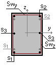
Section:
|
b = 1150 mm
|
S1 - 6Ø14
|

|
Reinforcement |
Class |
Service factor |
|
Longitudinal |
A400 |
1 |
|
Transverse |
A240 |
1 |
Concrete:
Concrete type: Heavy-weight
Concrete class: B15
|
Service factor for concrete |
||
|---|---|---|
|
γb1 |
allowance for the sustained loads |
1 |
|
γb2 |
allowance for the failure behavior |
1 |
|
γb3 |
allowance for the vertical position during concreting |
1 |
|
γb4 |
allowance for the freezing/thawing and negative temperatures |
1 |
Humidity of environmental air - 40-75%
Crack resistance:
Limited crack opening width
Requirements to crack opening width are based on the preservation of reinforcement
Allowable crack opening width:
Short-term opening 0,4 mm
Long-term opening 0,3 mm
Forces:
N = 0 kN
My = 60 kN*m
Qz = 0 kN
Mz = 0 kN*m
Qy = 0 kN
T = 0 kN*m
Factor for sustained load 0,83333
Theoretical solution:
Diagrams of the strain ε and stress σ distribution in concrete for the determination of the stress σs obtained in the theoretical calculation [2] based on the nonlinear deformation model are shown in Fig. 2. The following values of the internal longitudinal force N and bending moment M correspond to these diagrams
N = 0,00439 kN ≈ 0;
M = 50,096 ≈ 50 kNm.
There is a balance between internal and external forces. In this solution the stress in the tensile reinforcement is σs=236,692 MPa.

Figure 2. Strain e and stress s diagrams (for the determination of σs)
Similarly, solving the problem of determining the cracking moment, we obtain the following diagrams (Fig. 3), which satisfy the requirements of Sec. 8.2.14 of SP 63.13330.2012.

Figure 3. Strain e and stress s diagrams (for the determination of σs,crc)
In accordance with these diagrams Mcrc= 36,244 kN∙m, σs,crc = 22,651 MPa.
On the basis of formula (1) (formula (8.128) SP 63.13330.2012) we obtain acrc=0,306 mm.
| \[ a_{crc} =\varphi_{1} \cdot \varphi_{2} \cdot \varphi_{3} \cdot \psi_{s} \cdot \frac{\sigma_{s} }{E_{s} }\cdot l_{s} . \] | (1) |
Comparison of solutions:
|
Check |
crack opening width (long-term) |
|
Theory |
0,306/0,3 = 1,02 |
|
ARBAT |
0,974 |
|
Deviation, % |
4,51% |
Comments:
- The member length and the class of transverse reinforcement have to be specified in ARBAT. Since they are not determined in the problem, the following data are used 1 m and А240, respectively.
- The value of the concrete cover is equal to a – d/2 = 42 – 14/2 = 35 mm.
- The value of the total moment acting in the section, М = Ml + Msh = 50 + 10 = 60 kN∙m, factor for sustained load is equal to Ml /М = 50/60 = 0,833.
- The crack opening width obtained in the Guide [1] is equal to 0.227 mm. Such a significant discrepancy with the above theoretical solution is due to the use of the approach based on the ultimate forces, instead of the nonlinear deformation model (see [2]).
- The deviation of the results of ARBAT from the theoretical solution is due to the fact that in order to provide computational stability, diagrams in which the horizontal part of the graph σ(ε) has a small slope are used in ARBAT instead of the perfect diagrams of the material behavior.