Punching Analysis of a Flat Monolithic Floor Slab

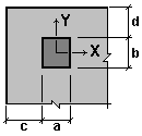
1 – force application point N; 2 – center of gravity of the open contour; 3 – open contour of the design section
Objective: Check the Punching mode.
Task: Verify the correctness of the punching strength analysis of a concrete element under a concentrated force and a bending moment when the load application area is near the edge of the slab.
References: Guide on designing of concrete and reinforced concrete structures made of heavy-weight concrete (no prestressing) (to SP 52-101-2003), 2005, p. 140-142.
Initial data file:
Example 41.SAV;
report:
when the analysis is performed according to SNiP 52-01-2003 – Arbat 41.1.doc,
when the analysis is performed according to SP 63.13330.2012 – Arbat 41.2.doc.
Compliance with the codes: SNiP 52-101-2003, SP 63.13330.2012.
Initial data from the source:
| h = 230 mm | Slab thickness |
| a×b = 500×400 mm | Column section sizes |
| N = 150 kN∙m | Load transferred from the floor slab to the column |
| Msup = 80 kN∙m | Moment in the column section on the upper face of the slab |
| Minf = 90 kN∙m | Moment in the column section on the lower face of the slab |
| x0 = 500 mm | Distance from the center of the column section to the free edge of the slab |
| Concrete class | В25 |
ARBAT initial data:
Importance factor γn = 1
Load application area is near the free edge of the element
|
|
a = 0,5 m |
Concrete:
Concrete type: Heavy-weight
Concrete class: B25
|
Service factor for concrete |
||
|---|---|---|
|
γb1 |
allowance for the sustained loads |
1 |
|
γb2 |
allowance for the failure behavior |
1 |
|
γb3 |
allowance for the vertical position during concreting |
1 |
|
γb4 |
allowance for the freezing/thawing and negative temperatures |
1 |
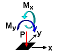
Loads:
|
|
P |
Mx |
My |
|---|---|---|---|
|
kN |
kN*m |
kN*m |
|
|
1 |
150 |
0 |
170 |
Forces:
P = 150 kN
Mx = 0 kN*m
My = 170 kN*m
Comparison of solutions (according to SP 52-101-2003):
|
Report file |
Arbat 41.1.doc |
|
|
Check |
punching strength of a concrete element under a concentrated force and bending moments with their vectors along X and Y axes |
punching strength of an unclosed concrete element under a concentrated force and bending moments (including additional ones caused by the eccentric application of a force with respect to the punched contour) with their vectors along X,Y-axes (load application area is near the edge of the slab) |
|
Guide |
203,4/210 = 0,969 |
202,2/210 = 0,963 |
|
ARBAT |
0,549 |
0,621 |
|
Deviation, % |
43,4% |
35,5% |
|
Analytical solution (see below) |
0,550 |
0,622 |
|
Deviation, % |
0,1 % |
0,1 % |
Comparison of solutions (according to SP 63.13330.2012):
|
Report file |
Arbat 41.2.doc |
|
|
Check |
punching strength of a concrete element under a concentrated force and bending moments with their vectors along X and Y axes |
punching strength of an unclosed concrete element under a concentrated force and bending moments (including additional ones caused by the eccentric application of a force with respect to the punched contour) with their vectors along X,Y-axes (load application area is near the edge of the slab) |
|
ARBAT |
0,413 |
0,466 |
|
Analytical solution (see below) |
0,412 |
0,466 |
|
Deviation, % |
0,1 % |
0 % |
Comments:
- The average effective height of the slab is taken as h0 = 200 mm in the calculation of the problem in the Guide. This value is used in ARBAT.
- The value of the sum of moments Msup and Minf on the upper and lower faces of the slab is used in ARBAT. Thus, M = 80 + 90 = 170 kN∙m.
- Distance from the edge of the load application area to the free edge of the slab с is equal to the difference between the distance from the center of the column section to the free edge of the slab and half the size of the column section in this direction: с = x0 – а/2 = 0,5 – 0,5/2 = = 0,25 m.
- In order to analyze the case when the (column) load transfer area is located near the edge of the flat element (floor slab), in ARBAT one of the values of the distance from the edge of the load application area to the free edge of the slab has to be greater than three times the effective height of the slab. Thus, d = 4 m > 3h0 = 0,6 m.
- Such significant differences in the obtained factors with the solution from the Guide are due to the following reasons:
- it is indicated in the codes that the calculations use the smallest values of the section moduli Wbx, determined from the following formulas:
\[ \mbox{W}_{bx} =\frac{\mbox{I}_{bx} }{\mbox{x}_{0} } \quad and \quad \mbox{W}_{bx} =\frac{\mbox{I}_{bx} }{\mbox{L}_{x} \mbox{-x}_{0} }. \]
In this problem the smaller value is the one determined by the first formula, since х0 = 0,5 + 0,0359 = 0,5359 m > Lx – х0 = 0,85 – 0,5359 = 0,3141 m (where х0 is the position of the center of gravity of the design open contour in the direction of the Х axis). Thus, the value Wbx determined by the first formula is used in ARBAT. While the value determined by the second formula is used in the Guide; - the check of the strength requirements in the Guide does not take into account the recommendations of the codes according to which under the action of concentrated moments and a force the ratio between the acting concentrated moments М, taken into account at punching, and the ultimate ones Mult should be taken not greater than the ratio between the acting concentrated force F and the ultimate one Fult (Sec. 6.2.46 of SNiP 52-101-2003) and not greater than half the ratio between the acting concentrated force F and the ultimate one Fult (Sec. 8.1.46 of SP 63.13330.2012).
- it is indicated in the codes that the calculations use the smallest values of the section moduli Wbx, determined from the following formulas:
- The analytical solution is given below.
Analytical solution

1 – closed design contour №1, 2 – open design contour №2, 3 – open design contour №3.
In this case it is necessary to check the strength of three contours of the design cross-section:
contour №1 – closed contour around the column section at a distance of 0,5h0 from the column contour;
contour №2 – open contour around the column section at a distance of 0,5h0 from the column contour with the extension of the contour to the free edge of the slab;
contour №3 – open contour around the column section at a distance of 0,5h0 from the column contour (contour of the verification analysis without the consideration of the reinforcement).
Closed contour №1:
Lx = Ax + h0 = 500 + 200 = 700 mm = 0,7 m,
Ly = Ay + h0 = = 400 + 200 = 600 mm = 0,6 m,
Perimeter of the design contour of the cross-section:
u = 2(Lx = Ly) = 2 (0,7 + 0,6) = 2,6 m.
Area of the design contour of the cross-section:
Ab = uh0 = 2,6 × 0,2 = 0,52 m2
Ultimate force resisted by concrete:
Fb,ult = RbtAb = 1,05 × 103 × 0,52 = 546 kN.
Moment of inertia of the design contour with respect to the X axis passing through its center of gravity:
\[ I_{bx} =2\frac{L_{y}^{3} }{12}+2L_{x} \left( {\frac{L_{y} }{2}} \right)^{2}= \quad 2\frac{0,6^{3} }{12}+2\cdot 0,7\left( {\frac{0,6}{2}} \right)^{2}=\quad 0,162 \quad m^{3}. \]
Section modulus of the design contour of concrete:
\[ W_{bx} =\frac{I_{bx} }{y_{\max } }= \quad \frac{0,162}{0,3}=\quad 0,54 \quad m^{2}. \]
Moment of inertia of the design contour with respect to the Y axis passing through its center of gravity:
\[ I_{by} =2\frac{L_{x}^{3} }{12}+2\cdot L_{y} \left( {\frac{L_{x} }{2}} \right)^{2}= \quad 2\frac{0,7^{3} }{12}+2\cdot 0,6\left( {\frac{0,7}{2}} \right)^{2}=\quad 0,204 \quad m^{3}. \]
Section modulus of the design contour of concrete:
\[ W_{by} =\frac{I_{by} }{x_{\max } }= \quad \frac{0,204}{0,35}=\quad 0,583 \quad m^{2}. \]
Bending moment which can be resisted by concrete in the design cross-section:
Mbx,ult = RbtWbxh0 = 1,05 × 103 × 0,54 × 0,2 = 113,4 kNm.
Mby,ult = RbtWbyh0 = 1,05 × 103 × 0,583 × 0,2 = 122,4 kNm.
For SNiP 52-101-2003:
 \[ \frac{M_{x} }{M_{bx,ult} }\le \frac{F}{F_{b,ult} }; \quad \frac{M_{y} }{M_{by,ult} }\le \frac{F}{F_{b,ult} } \] \( \frac{M_{y} }{M_{by,ult} }=\frac{85}{122,4}=0,694\le \frac{F}{F_{b,ult} }=\frac{150}{546}=0,275 \) – condition is not met.
Assume
\[ \frac{M_{y} }{M_{by,ult} }=\frac{F}{F_{b,ult} }=0,275 \]
Punching strength of the slab:
\[ K_{1} =\left[ {\frac{F}{F_{b,ult} }} \right.+\left. {\frac{M_{x} }{M_{bx,ult} }+\frac{M_{y} }{M_{by,ult} }} \right]\le 1,0 \]
\[ K_{1} = 0,275 + 0 + 0,275 = 0,55 \]
For SP 63.13330.2012:
\[ \frac{M_{x} }{M_{bx,ult} }+\frac{M_{y} }{M_{by,ult} }\le 0,5\frac{F}{F_{b,ult} } \]
\( \frac{M_{y} }{M_{by,ult} }=\frac{85}{122,4}=0,694\le 0,5\frac{F}{F_{b,ult} }=\frac{150}{546}=0,5\cdot 0,275=0,1375 \) – condition is not met.
Assume
\[ \frac{M_{y} }{M_{by,ult} }=\frac{F}{F_{b,ult} }=0,1375 \]
Punching strength of the slab:
\[ K_{1} =\left[ {\frac{F}{F_{b,ult} }} \right.+\left. {\frac{M_{x} }{M_{bx,ult} }+\frac{M_{y} }{M_{by,ult} }} \right]\le 1,0 \]
\[ K_{1} = 0,275 + 0 + 0,1375 = 0,413\]
Open contour №2:
Lx = Ax +h0 + 150 = 500 + 200 + 150 = 850 mm = 0,85 m,
Ly = Ay +h0= 400 + 200 = 600 mm = 0,6 m,
Perimeter of the design contour of the cross-section:
u = 2Lx +Ly = 2 × 0,85 + 0,6 = 2,3 m.
Area of the design contour of the cross-section:
Ab = uh0 2,3 × 0,2 = 0,46 m2.
X coordinate of the center of gravity of the open contour with respect to the left edge of the slab:
\[ X=\frac{425\cdot 850\cdot 2+850\cdot 600}{850\cdot 2+600}=535,869 mm \]
Ultimate force resisted by concrete:
Fb,ult = RbtAb =1,05 × 103 × 0,46 = 483 кН.
Moment of inertia of the design contour with respect to the X axis passing through its center of gravity:
\[ I_{bx} =\frac{L_{y}^{3} }{12}+2L_{x} \left( {\frac{L_{y} }{2}} \right)^{2}= \quad \frac{0,6^{3} }{12}+2\cdot 0,85\left( {\frac{0,6}{2}} \right)^{2}=\quad 0,171 \quad m^{3}. \]
Section modulus of the design contour of concrete:
\[ W_{bx} =\frac{I_{bx} }{y_{\max } }= \quad \frac{0,171}{0,3}=\quad 0,57 \quad m^{2}. \]
Moment of inertia of the design contour with respect to the Y axis passing through its center of gravity:
\[ I_{by} =2\frac{L_{x}^{3} }{12}+2L_{x} (0,075+0,035869)^{2}+L_{y} \left( {0,35-0,035869} \right)^{2}= 2\frac{0,85^{3} }{12}+2\cdot 0,85(0,075+0,035869)^{2}+0,6\left( {0,35-0,035869} \right)^{2}=0,183 \quad m^{3}. \]
Section modulus of the design contour of concrete:
\[ W_{by} =\frac{I_{by} }{x_{\max } }= \frac{0,183}{0,535869}= 0,341 \quad m^{2}. \]
Bending moment which can be resisted by concrete in the design cross-section:
Mbx,ult = RbtWbxh0 = 1,05 × 103 × 0,57 × 0,2 = 119,7 kNm.
Mby,ult = RbtWbyh0 = 1,05 × 103 × 0,341 × 0,2 = 71,6 kNm.
My = My - Fe0= 85 – 150 × 0,035869 = 85 – 5,38 = 79,62 kNm.
For SNiP 52-101-2003:
\[ \frac{M_{x} }{M_{bx,ult} }\le \frac{F}{F_{b,ult} }; \quad \frac{M_{y} }{M_{by,ult} }\le \frac{F}{F_{b,ult} } \]
\( \frac{M_{y} }{M_{by,ult} }=\frac{79,62}{71,6}=1,112\le \frac{F}{F_{b,ult} }=\frac{150}{483}=0,311 \) – condition is not met.
Assume
\[ \frac{M_{y} }{M_{by,ult} }=\frac{F}{F_{b,ult} }=0,311 \]
Punching strength of the slab:
\[ K_{1} =\left[ {\frac{F}{F_{b,ult} }} \right.+\left. {\frac{M_{x} }{M_{bx,ult} }+\frac{M_{y} }{M_{by,ult} }} \right]\le 1,0 \] \[ K_{1} \quad = \quad 0,311+0+0,311 = 0,622 \]
For SP 63.13330.2012:
\[ \frac{M_{x} }{M_{bx,ult} }+\frac{M_{y} }{M_{by,ult} }\le 0,5\frac{F}{F_{b,ult} } \]
\( \frac{M_{y} }{M_{by,ult} }=\frac{79,62}{71,6}=1,112\le 0,5\frac{F}{F_{b,ult} }=\frac{150}{483}=0,5\cdot 0,311=0,155 \) – condition is not met.
Assume
\[ \frac{M_{y} }{M_{by,ult} }=\frac{F}{F_{b,ult} }=0,155 \]
Punching strength of the slab:
\[ K_{1} =\left[ {\frac{F}{F_{b,ult} }} \right.+\left. {\frac{M_{x} }{M_{bx,ult} }+\frac{M_{y} }{M_{by,ult} }} \right]\le 1,0 \] \[ K_{1} \quad = 0,311 + 0 + 0,155 = 0,466 \]
Open contour №3:
Lx = Ax + 2 × 1,5h0 = 500 + 1,5 × 200 + 250 = 1050 мм = 1,05 m,
Ly = Ay + 2 × 1,5h0 = 400 + 2 × 1,5 × 200 = 1000 мм = 1,0 m,
Perimeter of the design contour of the cross-section:
u = 2Lx + Ly = 2 × 1,05 + 1,0 = 3,1 m.
Area of the design contour of the cross-section:
Ab = uh0 = 3,1 × 0,2 = 0,62 m2.
X coordinate of the center of gravity of the open contour with respect to the left edge of the slab:
\[ X=\frac{525\cdot 1050\cdot 2+1050\cdot 1000}{1050\cdot 2+1000}=694,355 \quad mm \]
Ultimate force resisted by concrete:
Fb,ult = RbtAb = 1,05 × 103 × 0,62 = 651 kN.
Moment of inertia of the design contour with respect to the X axis passing through its center of gravity:
\[ I_{bx} =\frac{L_{y}^{3} }{12}+2L_{x} \left( {\frac{L_{y} }{2}} \right)^{2}= \quad \frac{1,05^{3} }{12}+2\cdot 1,05\left( {\frac{1,0}{2}} \right)^{2}=\quad 0,608 \quad m^{3}. \]
Section modulus of the design contour of concrete:
\[ W_{bx} =\frac{I_{bx} }{y_{\max } }= \quad \frac{0,608}{0,5}=\quad 1,217 \quad m^{2}. \]
Moment of inertia of the design contour with respect to the Y axis passing through its center of gravity:
\[ I_{by} =2\frac{L_{x}^{3} }{12}+2L_{x} (0,194355-0,025)^{2}+L_{y} \left( {1,05-0,694355} \right)^{2}= 2\frac{1,05^{3} }{12}+2\cdot 1,05(0,194355-0,025)^{2}+1,0\left( {1,05-0,694355} \right)^{2}=0,38 \quad m^{3}. \]
Section modulus of the design contour of concrete:
\[ W_{by} =\frac{I_{by} }{x_{\max } }= \quad \frac{0,38}{0,694355}=\quad 0,547 \quad m^{2}. \]
Bending moment which can be resisted by concrete in the design cross-section:
Mbx,ult = RbtWbxh0 = 1,05 × 103 × 1,217 × 0,2 = 255,57 kNm.
Mby,ult = RbtWbyh0 =1,05 × 103 × 0,547 × 0,2 = 114,87 kNm.
My = My – Fe0 =85 – 150 × 0,194355 = 85 – 29,15 = 55,85 kNm.
For SNiP 52-101-2003:
\[ \frac{M_{x} }{M_{bx,ult} }\le \frac{F}{F_{b,ult} }; \quad \frac{M_{y} }{M_{by,ult} }\le \frac{F}{F_{b,ult} } \]
\( \frac{M_{y} }{M_{by,ult} }=\frac{55,85}{114,87}=0,486\le \frac{F}{F_{b,ult} }=\frac{150}{651}=0,23 \) – condition is not met.
Assume
\[ \frac{M_{y} }{M_{by,ult} }=\frac{F}{F_{b,ult} }=0,23 \]
Punching strength of the slab:
\[ K_{1} =\left[ {\frac{F}{F_{b,ult} }} \right.+\left. {\frac{M_{x} }{M_{bx,ult} }+\frac{M_{y} }{M_{by,ult} }} \right]\le 1,0 \] \[ K_{1} \quad = 0,23 + 0 + 0,23 = 0,46 \]
For SP 63.13330.2012:
\[ \frac{M_{x} }{M_{bx,ult} }+\frac{M_{y} }{M_{by,ult} }\le 0,5\frac{F}{F_{b,ult} } \]
\( \frac{M_{y} }{M_{by,ult} }=\frac{55,85}{114,87}=0,486\le 0,5\frac{F}{F_{b,ult} }=\frac{150}{651}=0,5\cdot 0,23=0,115 \) – condition is not met.
Assume
\[ \frac{M_{y} }{M_{by,ult} }=\frac{F}{F_{b,ult} }=0,155 \]
Punching strength of the slab:
\[ K_{1} =\left[ {\frac{F}{F_{b,ult} }} \right.+\left. {\frac{M_{x} }{M_{bx,ult} }+\frac{M_{y} }{M_{by,ult} }} \right]\le 1,0 \] \[ K_{1} \quad = 0,23 + 0 + 0,115 = 0,345 \]