Calculation of a Column of a Multi-storey Frame for Load-bearing Capacity under a Lateral Force
Objective: Check of the calculation of the resistance of reinforced concrete sections.
Task: Verify the correctness of the strength analysis of oblique sections.
References: Guide on designing of concrete and reinforced concrete structures made of heavy-weight concrete (no prestressing) (to SNiP 52-101-2003), 2005, p. 104-105.
Initial data file:
Example 34.SAV;
report:
when the analysis is performed according to SNiP 52-01-2003 – Arbat 34.1.doc,
when the analysis is performed according to SP 63.13330.2012 – Arbat 34.2.doc.
Compliance with the codes: SNiP 52-101-2003, SP 63.13330.2012.
Initial data from the source:
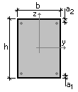
| b×h = 400×600 mm | Column section sizes |
| l = 3,3 m | Column length (distance between support sections) |
| а = а' = 50 mm | Distance from the center of gravity of the longitudinal reinforcement to the fiber of the section under the greatest tension |
| d = 12 mm | Diameter of transverse reinforcement |
| sw = 400 mm | Spacing of transverse reinforcement |
| Msup = 350 kN∙m | Bending moment in the upper support section |
| Minf = 250 kN∙m | Bending moment in the lower support section |
| N = 572 kN | Longitudinal force |
| Concrete class | В25 |
| Class of transverse reinforcement | А240 |
ARBAT initial data:
Importance factor γn = 1
Importance factor (serviceability limit state) = 1
Member length 3,3 m
Effective length factor in the XoY plane 1
Effective length factor in the XoZ plane 1
Random eccentricity along Z according to SNiP 52-01-2003 (Russia)
Random eccentricity along Y according to SNiP 52-01-2003 (Russia)
Structure is statically indeterminate
Limit slenderness - 200
Section
|
|
|

|
Reinforcement |
Class |
Service factor |
|
Longitudinal |
A400 |
1 |
|
Transverse |
A240 |
1 |
Concrete
Concrete type: Heavy-weight
Concrete class: B25
|
Service factor for concrete |
||
|---|---|---|
|
γb1 |
allowance for the sustained loads |
1 |
|
γb2 |
allowance for the failure behavior |
1 |
|
γb3 |
allowance for the vertical position during concreting |
1 |
|
γb4 |
allowance for the freezing/thawing and negative temperatures |
1 |
Humidity of environmental air - 40-75%
Crack resistance:
No cracks
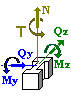
Forces
|
|
N |
My |
Qz |
Mz |
Qy |
T |
Safety factor for load |
Factor for sustained load |
Short-term |
Seismic |
|---|---|---|---|---|---|---|---|---|---|---|
|
kN |
kN*m |
kN |
kN*m |
kN |
kN*m |
|||||
|
1 |
-572 |
600 |
181,8 |
0 |
0 |
0 |
1 |
1 |
|
|
Comparison of solutions (according to SNiP 52-101-2003):
|
File |
Example 34.SAV |
|
Report file |
Arbat 34.1.doc |
|
Check |
strength for an oblique section |
|
Guide |
181,8/184,8 = 0,984 |
|
ARBAT |
0,982 |
|
Deviation, % |
0,17 % |
Comparison of solutions (according to SP 63.13330.2012):
|
File |
Example 34.SAV |
|
Report file |
Arbat 34.2.doc |
|
Check |
strength for an oblique section |
|
Guide |
181,8/184,8 = 0,984 |
|
ARBAT |
0,898 |
|
Deviation, % |
8,7% |
Comments:
- Bending moment My is determined as a sum of moments in the upper and lower support sections My = Msup + Minf = 350 + 250 = 600 kN.
- The lateral force in the column is determined as: Qz = My/l = 600/3,3 = 181,8 kN.
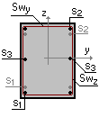
- The data on the longitudinal reinforcement has to be specified in ARBAT. Since it is not defined in the problem, the following reinforcement is used: class А400, rebars 2Ø6. Respectively, the value of the concrete cover is а1 = а2 = а – d/2 = 50 – 6/2 = 47 mm.
- The difference between the utilization factors of 14,3% in the results of the solution in the Guide and in ARBAT according to SP 63.13330.2012 is due to the fact that compressive stresses are taken into account in different ways according to the given codes (Sec. 8.1.34) and according to SNiP 52-101-2003.