Strength and Stiffness Analysis of Secondary Beams for a Complex Stub Girder System
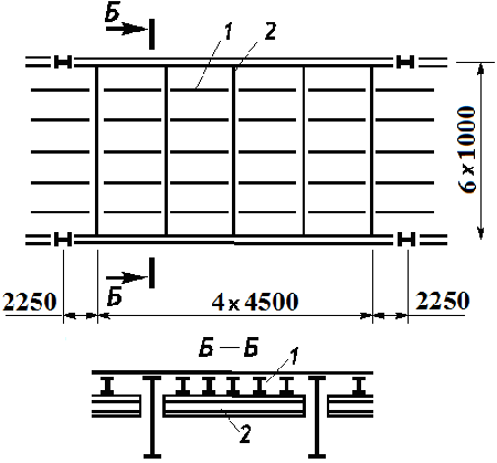
1 – stringer
2 – secondary beam
Objective: Check the mode for calculating and selecting beams
Task: Select a rolled I-beam for the secondary beams with a span of 6 m in a complex stub girder system. The top chord of the secondary beams is restrained by the stringers arranged with a spacing of 1 m.
References: Steel Structures: Student Handbook / [Kudishin U.I., Belenya E.I., Ignatieva V.S and others] - 13-th ed. rev. - M.: Publishing Center "Academy", 2011. p. 183.
Compliance with the codes: SNiP II-23-81*, SP 16.13330, DBN B.2.6-163:2010.
Initial data file:
3.3.sav;
report — Kristall 3.3.doc
Initial data:
| а = 4,5 m | Spacing of secondary beams; |
| qн = (0,77 + 27,3/102 + 20) kN/m2 × 4,5 m = 94,67 kN/m | Total characteristic load; |
| q1 = 1,05×(0,77 + 27,3/102) kN/m2 × 4,5 m = 4,9 kN/m | Design permanent load; |
| q2 = 1,2×20 kN/m2 × 4,5 m = 108 kN/m | Design temporary load; |
| Ry = 23 kN/cm2, | Steel grade C235; |
| l = 6,0 m | Beam span; |
| [ f ] = 1/250×6,0 m = 24 mm | Limit deflection; |
| γc = 1 | Service factor; |
| Wy = 2034,98 cm3 | Selected I-beam No.55 GOST 8239-89; |
| Iy = 55962 cm4. |
KRISTALL parameters:
Steel: C235
Group of structures according to the table 50* of SNiP II-23-81* 4
Importance factor γn = 1
Importance factor (serviceability limit state) = 1
Service factor 1

Structure:

Restraints against lateral displacements and rotations:
|
|
Left |
Right |
|---|---|---|
|
Displacement along Y |
Restrained |
Restrained |
|
Displacement along Z |
Restrained |
Restrained |
|
Rotation about Y |
|
|
|
Rotation about Z |
|
|
Restraints out of the bending plane  n=6
n=6
Section:

Profile: I-beam with sloped inner flange surfaces GOST 8239-89 55
Manual calculation:
1. Design bending moment acting in the beam span:
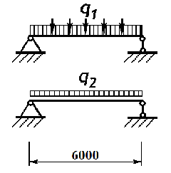
\[ M_{\max } =\frac{q_{\Sigma } l^{2}}{8}=\frac{\left( {4,9+108} \right)\cdot 6,0^{2}}{8}=508,05 \quad kNm. \]
2. Necessary beam section modulus assuming that the deformations of steel are elastic:
\[ W_{nes} =\frac{M_{\max } }{R_{y} }=\frac{508,05\cdot 100}{23}=2208,913 \quad cm^{3}. \]
3. Maximum deflection occurring in the middle of the beam span:
\[ f_{\max } =\frac{5}{384}\cdot \frac{q_{н} l^{4}}{EI_{y} }=\frac{5}{384}\cdot \frac{94,67\cdot 6,0^{4}}{2,06\cdot 10^{5}\cdot 10^{3}\cdot 55962\cdot 10^{-8}}=13,858 \quad mm. \]
4. Conditional limit slenderness of the compressed beam chord:
\[ \bar{{\lambda }}_{ub} =0,35+0,0032\frac{b_{f} }{t_{f} }+\left( {0,76-0,02\frac{b_{f} }{t_{f} }} \right)\frac{b_{f} }{h_{f} }=0,35+0,0032\frac{180}{16,5}+\left( {0,76-0,02\frac{180}{16,5}} \right)\frac{180}{533,5}=0,5677. \]
5. Conditional actual slenderness of the compressed beam chord:
\( \bar{{\lambda }}_{b} =\frac{l_{ef} }{b_{f} }\sqrt {\frac{R_{y} }{E}} =\frac{1000}{180}\sqrt {\frac{230}{2,06\cdot 10^{5}}} =0,1856<\bar{{\lambda }}_{ub} =0,5677 \) – проверка устойчивости не требуется.
Comparison of solutions:
|
Factor |
Strength under action of lateral force |
Strength under action of bending moment |
Stability of in-plane bending under moment |
Maximum deflection |
|---|---|---|---|---|
|
Manual calculation |
– |
2208,913/2034,98 =1,085 |
– |
13,858/24 = 0,577 |
|
KRISTALL |
0,488 |
1,085 |
1,085 |
13,856/24 = 0,577 |
|
Deviation from the manual calculation, % |
0,0 |
0,0 |
0,0 |
0,0 |
|
Source |
– |
0,99 |
– |
0,58 |
Comments:
- The check of tangential stresses was not performed in the manual calculation due to the absence of weakenings and a relatively large thickness of the beam webs.
- In the source the check of the beam strength under the action of the bending moment was performed taking into account the development of the limited plastic deformations.
- The check of the beam strength taking into account the development of the limited plastic deformations was not performed, because according to the codes this calculation is possible only when the beam web has stiffeners. In the initial data of the example a rolled beam without intermediate stiffeners was selected for the secondary beam.