Strength and Stiffness Analysis of Main Beams of Complex Stub Girder Systems
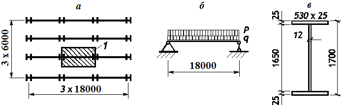
a – floor plan; b – design model of the main beam; c – beam section;
1 – load area
Objective: Check the mode for calculating and selecting beams
Task: Select a welded I-beam for the main beams with a span of 18 m in a normal stub girder system. The top chord of the main beams is restrained by the stringers arranged with a spacing of 1 m.
References: Steel Structures: Student Handbook / [Kudishin U.I., Belenya E.I., Ignatieva V.S and others] - 13-th ed. rev. - M.: Publishing Center "Academy", 2011. p. 192.
Compliance with the codes: SNiP II-23-81*, SP 16.13330, DBN B.2.6-163:2010.
Initial data file:
3.4.sav;
report — Kristall3.4.doc
Initial data:
| а = 6 m | Spacing of main beams; |
| g1 = 1,16 kN/m2 | Weight of the floor plate and stringers; |
| p = 20 kN/m2 | Temporary (live) load; |
| qн = 127,099 kN/m | Total characteristic load on the beam; |
| q1 = 1,05*1,16 kN/m2 * 6 m*1,02 = 7,454 kN/m |
Design permanent load;(coefficient 1,02 allows for the self-weight of the main beam); |
| q2 = 1,2*20 kN/m2 * 6 m = 144,0 kN/m | Design live load; |
| l = 18 m | Main beam span; |
| Ry = 23 kN/cm2 Rs = 0,58*23=13,34 kN/cm2 |
Steel grade C255 with thickness t>20 mm; |
| [ f ] = l/400 = 45 mm | Limit deflection; |
| bp×tp = 530×20 mm | Section of the bearing stiffener; |
| kp = 6 mm | Fillet weld leg in a welded connection between a bearing stiffener and a beam; |
| γc = 1 | Service factor; |
| Wy = 27153,85 cm3 | Geometric properties for a welded |
| Iy = 2308077,083 cm4 | I-section with flanges 530×25 mm and a web 1650×12 mm |
| Sy = 15180,625 cm3. |
KRISTALL parameters:
Steel: C255
Group of structures according to the table 50* of SNiP II-23-81* 3
Importance factor γn = 1
Importance factor (serviceability limit state) = 1
Service factor 1

Structure:

Restraints against lateral displacements and rotations:
|
|
Left |
Right |
|---|---|---|
|
Displacement along Y |
Restrained |
Restrained |
|
Displacement along Z |
Restrained |
Restrained |
|
Rotation about Y |
|
|
|
Rotation about Z |
|
|
Restraints out of the bending plane  n=17
n=17
Leg of girth welds – 8 mm
Leg of welds that attach the bearing stiffener – 6 mm
Section:

Manual calculation (SNiP II-23-81*):
1. Maximum bending moment and shear force acting in the design sections of the beam:
\[ M_{\max } =\frac{q_{\Sigma } l^{2}}{8}=\frac{\left( {7,454+144} \right)\cdot 18,0^{2}}{8}=6133,887 \quad kNм. \] \[ Q_{\max } =\frac{q_{\Sigma } l}{2}=\frac{\left( {7,454+144} \right)\cdot 18,0}{2}=1363,086 \quad kN. \]
2. Necessary beam section modulus:
\[ W_{nes} =\frac{M_{\max } }{R_{y} \gamma_{c} }=\frac{6133,887\cdot 100}{23}=26669,074 \quad cm^{3}. \]
3. Maximum tangential stresses in the support section of the beam:
\[ \tau_{\max } =\frac{Q_{\max } S_{y} }{I_{y} t_{w} }=\frac{1363,086\cdot 15180,625}{2308077,083\cdot 1,2}=7,471 \quad kN/cm^{2}. \]
4. Maximum deflection occurring in the middle of the beam span:
\[ f_{\max } =\frac{5}{384}\cdot \frac{q_{н} l^{4}}{EI_{y} }=\frac{5}{384}\cdot \frac{127,099\cdot 18,0^{4}}{2,06\cdot 10^{5}\cdot 10^{3}\cdot 2308077,083\cdot 10^{-8}}=36,539 \quad мм. \]
5. Conditional limit slenderness of the compressed beam chord:
\[ \bar{{\lambda }}_{ub} =0,35+0,0032\frac{b_{f} }{t_{f} }+\left( {0,76-0,02\frac{b_{f} }{t_{f} }} \right)\frac{b_{f} }{h_{f} }=0,35+0,0032\frac{530}{25}+\left( {0,76-0,02\frac{530}{25}} \right)\frac{530}{1675}=0,524. \]
6. Conditional actual slenderness of the compressed beam chord:
\( \bar{{\lambda }}_{b} =\frac{l_{ef} }{b_{f} }\sqrt {\frac{R_{y} }{E}} =\frac{1000}{530}\sqrt {\frac{230}{2,06\cdot 10^{5}}} =0,063<\bar{{\lambda }}_{ub} =0,524 \) – проверка устойчивости не требуется.
7. Conditional slenderness of the overhang of the compressed beam flange:
\[ \bar{{\lambda }}_{f} =\frac{b_{ef} }{t_{f} }\sqrt {\frac{R_{y} }{E}} =\frac{b_{f} -t_{w} }{2t_{f} }\sqrt {\frac{R_{y} }{E}} =\frac{530-12}{2\cdot 25}\sqrt {\frac{230}{2,06\cdot 10^{5}}} =0,346<\bar{{\lambda }}_{uf} =0,5. \]
8. 8. Strength of the bearing stiffener at the bearing of its end surface (\( (R_{un} =370 \quad MPa,\), \(R_{p} =\frac{370}{1,025}=360,98 \quad MPa \) (cm. табл. 1*)):
\[ N_{p} =A_{p} R_{p} =53,0\cdot 2\cdot 36,098=3826,388 \quad kN. \]
9. Reduced area, moment of inertia and slenderness of the bearing stiffener in the analysis of its stability:
\[ A_{red} =b_{p} t_{p} +0,65t_{w}^{2} \sqrt {\frac{E}{R_{y} }} =53,0\cdot 2,0+0,65\cdot 1,2^{2}\sqrt {\frac{2,06\cdot 10^{5}}{230}} =134,012 \quad cm^{2}; \] \[ I_{p} =\frac{1}{12}\left( {t_{p} b_{p}^{3} +0,65t_{w}^{4} \sqrt {\frac{E}{R_{y} }} } \right)=\frac{1}{12}\left( {2,0\cdot 53,0^{3}+0,65\cdot 1,2^{4}\sqrt {\frac{2,06\cdot 10^{5}}{230}} } \right)=24816,1948 \quad cm^{4}. \] \[ \lambda_{p} =l_{ef} \sqrt {\frac{A_{red} }{I_{p} }} =\left( {165+2,5} \right)\cdot \sqrt {\frac{134,012}{24816,1948}} =12,309; \] \[ \bar{{\lambda }}_{p} =\lambda_{p} \sqrt {\frac{R_{y} }{E}} =12,309\cdot \sqrt {\frac{230}{2,06\cdot 10^{5}}} =0,411. \]
10. Buckling coefficient of the bearing stiffener of the beam:
\[ \varphi =1-\left( {0,073-5,53\frac{R_{y} }{E}} \right)\bar{{\lambda }}_{p} \sqrt {\bar{{\lambda }}_{p} } =1-\left( {0,073-5,53\cdot \frac{230}{2,06\cdot 10^{5}}} \right)0,411\sqrt {0,411} =0,9824. \]
11. Load-bearing capacity of the bearing stiffener from the condition of providing its stability:
\[ N_{p,b} =\varphi A_{red} R_{y} =0,9824\cdot 134,012\cdot 23,0=3028,028 \quad kN. \]
12. Load-bearing capacity of the fillet welds attaching the bearing stiffener to the beam web:
\[ N_{f} =2\beta_{f} k_{f} l_{f} R_{wf} \gamma_{wf} =2\beta_{f} k_{f} \left( {85\beta_{f} k_{f} } \right)R_{wf} \gamma_{wf} =2\cdot 0,7\cdot 0,6\cdot \left( {85\cdot 0,7\cdot 0,6} \right)\cdot 18,0\cdot 1,0=539,784 \quad kN. \]
13. Load-bearing capacity per unit length of fillet welds attaching the beam flanges to the web:
\[ N_{f} =2\beta_{f} k_{f} R_{wf} \gamma_{wf} =2\cdot 0,7\cdot 0,8\cdot 18,0\cdot 1,0=20,16 \quad kN/cm. \]
14. Shear force per unit length acting on the fillet welds attaching the beam flanges to the web:
\[ T=\frac{Q_{\max } S_{yf} }{I_{y} }=\frac{1363,086\cdot 53,0\cdot 2,5\cdot 83,75}{2308077,083}=6,5535 \quad kN/cm. \]
Comparison of solutions:
|
Factor |
Source |
Manual calculation |
KRISTALL |
Deviation, % |
|---|---|---|---|---|
|
Stability of bearing stiffener |
– |
1363,086/3028,028 = 0,450 |
0,45 |
0,0 |
|
Bearing stiffener in bearing |
– |
1363,086/3826,388 = 0,356 |
0,357 |
0,0 |
|
Strength of girth weld |
– |
6,5535/20,16 = 0,325 |
0,315 |
1,23% |
|
Strength of bearing stiffener weld |
– |
1363,086/539,784 = 2,525 |
2,525 |
0,0 |
|
Strength under action of lateral force |
0,617 |
7,471/13,34 = 0,56 |
0,56 |
0,0 |
|
Strength under action of bending moment |
1,0 |
26669,074/27153.85=0,982 |
0,982 |
0,0 |
|
Stability of in-plane bending under moment |
– |
– |
0,982 |
0,0 |
|
Local stability of web |
– |
– |
0,6 |
0,0 |
|
Local stability of chord overhang |
0,71 |
0,346/0,5 = 0,692 |
0,692 |
0,0 |
|
Maximum deflection |
– |
36,539/45 = 0,812 |
0,812 |
0,0 |
Comments:
- In the source the check of the tangential stresses was performed according to the approximate formula.
- The check of the local stability of the chord overhang performed in the source is incorrect.