Analysis of the Base of a Solid I-beam Column

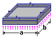
Design models of the column base (figures in the circles indicate the numbers of the design sections of the base plate: 1 – wing plate; 2 – base plate)
Objective: Check the mode for calculating base plates
Task: Check the load-bearing capacity of the base plate for the design section No.1.
Source: Steel Structures: Student Handbook / [Kudishin U.I., Belenya E.I., Ignatieva V.S and others] - 13-th ed. rev. - M.: Publishing Center "Academy", 2011. p. 259.
Compliance with the codes: SNiP II-23-81*, SP 16.13330, DBN B.2.6-163:2010.
Initial data file:
6.1.sav;
report — Kristall-6.1.doc
Initial data:
| σf = 1,19 kN/cm2 = 11,9 MPa | Stress under the base plate |
| Ry = 30 kN/cm2 | Steel grade C345 |
| b/a = 480 mm / 234 mm | Dimensions of the design section of the base plate |
KRISTALL parameters:
Steel: C345 category 1
Group of structures according to the table 50* of SNiP II-23-81* 3
Importance factor 1
Service factor 1,15
|
|
a = 0.48 m |
Manual calculation (SNiP II-23-81*):
1. Design bending moment acting in the design section of the base plate:
\[ M=\alpha \sigma_{f} a^{2}=0,125\cdot 1,19\cdot 23,4^{2}=81,45 \quad kN/cm. \]
2. Check the bending strength of the base plate ( γc = 1,15 – according to the table 6* of SNiP II-23-81*):
\[ \frac{6M}{t_{p}^{2} }=\frac{6\cdot 81,45}{4^{2}}=30,5436 \quad kN/cm^{2} \quad\quad < R_{y} \gamma_{c} =30\cdot 1,15=34,5 \quad kN/cm^{2}. \]
Comparison of solutions:
|
Factor |
Source |
Manual calculation |
KRISTALL |
Deviation from the manual calculation, % |
|---|---|---|---|---|
|
for bending strength of the plate |
4/4=1 |
30,5436/34,5 = 0,885 |
0,885 |
0,0 |
Comments:
The service factor of the base plate according to the table 6* of SNiP II-23-81* is not taken into account in the source.