Plane Truss Subjected to a Concentrated Force

Objective: Determination of the stress-strain state of a plane truss subjected to a concentrated force.
Initial data file: SSLL09_v11.3.spr
Problem formulation: The plane truss consists of two inclined downward bars of the same length and rigidity of the cross-section arranged symmetrically with respect to the vertical axis, connected by hinges in the common node (point C) and simply supported at the opposite nodes (points A and B). A vertical concentrated force F is applied in the common node of the truss bars. Determine the vertical displacement of the common node of the truss bars Z and longitudinal forces in the truss bars N.
References: S. Timoshenko, Resistance des materiaux, t.1, Bruxelles, Edition Polytechnique Beranger, 1963, p. 10.
Initial data:
| E = 2.1·1011 Pa | - elastic modulus of truss bars; |
| l = 4.5 m | - length of truss bars; |
| θ = 30º | - inclination angle of the bars to the horizon; |
| A = 3.0·10-4 m2 | - cross-sectional area of the bars; |
| F = 2.1·104 N | - value of the vertical concentrated force. |
Finite element model: Design model – plane hinged bar system, 2 bar elements of type 10. Boundary conditions are provided by imposing constraints in the directions of the degrees of freedom X, Z for pinned support nodes. Number of nodes in the design model – 3.
Results in SCAD
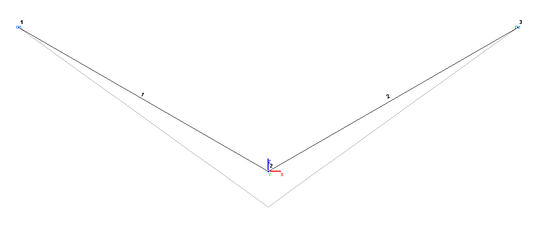
Design and deformed models
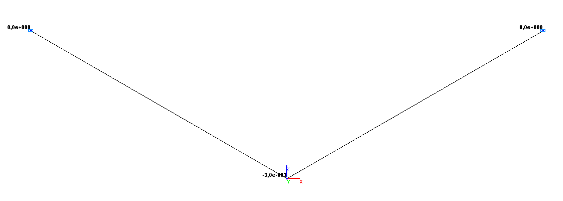
Values of vertical displacements Z (m)
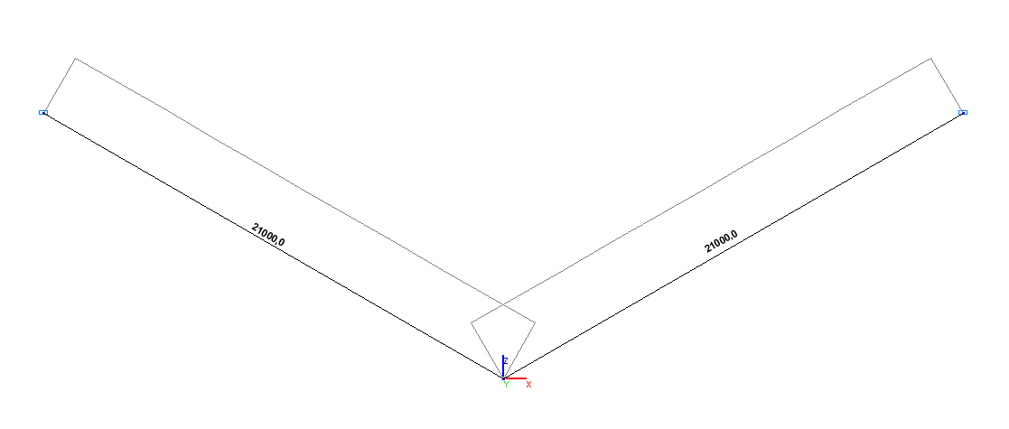
Values of longitudinal forces N (N)
Comparison of solutions:
|
Parameter |
Theory |
SCAD |
Deviations, % |
|---|---|---|---|
|
Vertical displacement Z (point C), m |
-3.0000·10-3 |
-3.0000·10-3 |
0.00 |
|
Longitudinal force N (bar AC), N |
21000.0 |
21000.0 |
0.00 |
|
Longitudinal force N (bar BC), N |
21000.0 |
21000.0 |
0.00 |
Notes: In the analytical solution, the vertical displacement of the common node of the truss bars Z and longitudinal forces in the truss bars N are determined according to the following formulas:
\[ Z=\frac{F\cdot L}{2\cdot E\cdot A\cdot \sin^{2}\left( \theta \right)}; \]
\[ N=\frac{F}{2\cdot \sin \left( \theta \right)}. \]