Simply Supported Beam Subjected to a Concentrated Force and Uniformly Distributed Pressure

Objective: Combined loading (lateral pressure, concentrated force) in one plane without taking into account the transverse shear deformations. Displacements and forces are checked.
Initial data file: 4_3.spr
Problem formulation: The simply supported beam is subjected to a concentrated force Р and uniformly distributed pressure q. Displacements w, rotation angles θ, shear forces Q and bending moments М are determined.
References: G.S. Pisarenko, A.P. Yakovlev, V.V. Matveev, Handbook on Strength of Materials. — Kiev: Naukova Dumka, 1988.
Initial data:
| E = 2.0·1011 Pa | - elastic modulus; |
| μ = 0.3 | - Poisson’s ratio; |
| l = 3 m | - beam length; |
| F = 14.2·10-4 m2 | - cross-sectional area; |
| I = 2.44·10-6 m4 | - moment of inertia; |
| Р = −5 kN | - value of the concentrated force; |
| q = 10 kN/m | - value of pressure; |
| a = b = 1.5 m | - geometric size. |
Finite element model:
Design model – plane frame, 10 bar elements, 11 nodes.
Results in SCAD
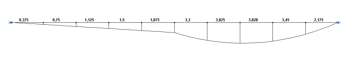
Bending moment diagram М (kN*m)
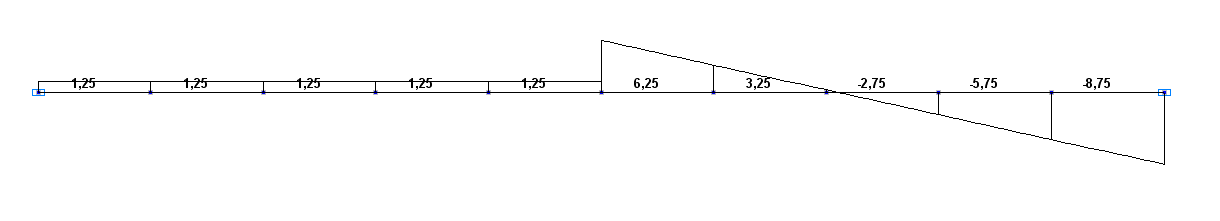
Shear force diagram Q (kN)
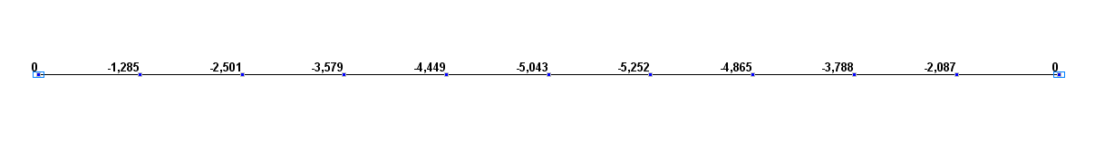
Values of transverse displacements w (mm)
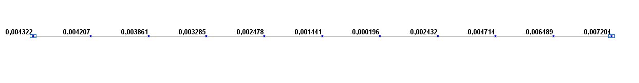
Values of rotation angles θ (rad)
Comparison of solutions:
|
Parameter |
Theory |
SCAD |
Deviations, % |
|---|---|---|---|
|
Deflection in the point С, mm |
-5.043 |
-5.043 |
0.00 |
|
Rotation angle in the point В, rad |
-7.204·10-3 |
-7.204·10-3 |
0.00 |
|
Bending moment in the point С, kN·m |
1.875 |
1.875 |
0.00 |
|
Shear force in the point A, kN |
1.25 |
1.25 |
0.00 |
|
Shear force in the point B, kN |
-8.75 |
-8.75 |
0.00 |
Notes: In the analytical solution, the deflection in the point C can be calculated according to the following formula (“Handbook on Strength of Materials” p. 295, 297):
\[ w_{C} =\frac{P\cdot a^{2}\cdot b^{2}}{3\cdot E\cdot I\cdot \left( {a+b} \right)}+\frac{q\cdot a\cdot b^{3}\cdot \left( {4\cdot a+b} \right)}{24\cdot E\cdot I\cdot \left( {a+b} \right)}. \]
The rotation angle in the point B can be calculated according to the following formula (“Handbook on Strength of Materials” p. 295, 297):
\[ \theta_{B} =\frac{P\cdot b\cdot \left( {2\cdot a^{2}+a\cdot b} \right)}{6\cdot E\cdot I\cdot \left( {a+b} \right)}-\frac{q\cdot b^{2}\cdot \left( {4\cdot a^{2}+4\cdot a\cdot b+b^{2}} \right)}{24\cdot E\cdot I\cdot \left( {a+b} \right)}. \]
The bending moment in the point C can be calculated according to the following formula:
\[ M_{C} =\frac{P\cdot a\cdot b}{a+b}+\frac{q\cdot a\cdot b^{2}}{2\cdot \left( {a+b} \right)}. \]
The shear force in the point A can be calculated according to the following formula:
\[ Q_{A} =\frac{P\cdot b}{a+b}+\frac{q\cdot b^{2}}{2\cdot \left( {a+b} \right)}. \]
The shear force in the point B can be calculated according to the following formula:
\[ Q_{B} =-\frac{P\cdot a}{a+b}-\frac{q\cdot \left( {2\cdot a+b} \right)\cdot b}{2\cdot \left( {a+b} \right)}. \]