Flexible Square Plate Simply Supported along the Perimeter Subjected to a Uniformly Distributed Transverse Load
Objective: Determination of maximum displacements and longitudinal stresses in a flexible square plate simply supported along the perimeter and subjected to a uniformly distributed transverse load in the geometrically nonlinear formulation.
Initial data file: 7.6.spr
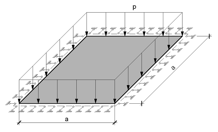
Problem formulation: The flexible square isotropic plate of constant thickness is simply supported along the perimeter and subjected to the uniformly distributed transverse load p. Determine: the transverse displacements w and longitudinal stresses Nx and Ny for the center of the plate.
References: S. Levy, Bending of rectangular plates with large deflections, Washington, National advisory committee for aeronautics, Technical note No 846, May 1942.
H. Hencky, Die berechnung dünner rechteckiger platten mit verschwindender biegungsteifigkeit, Dresden, Zeitschrift für angewandte mathematic und mechanic, April 1921.
I.A. Birger, Ya.G. Panovko, Strength, Stability, Vibrations, Handbook in three volumes, Volume 1, Moscow, Mechanical engineering, 1968, p. 606
Initial data:
| E = 2.0·108 kPa | - elastic modulus of the plate material; |
| ν = 0.3 | - Poisson’s ratio; |
| h = 0.01 m | - thickness of the plate; |
| a = 10.0 m | - side of the plate; |
| p = 10 kPa | - value of the uniformly distributed load. |
Finite element model: Design model – general type system. Plate elements - 10000 four-node shell elements taking into account the geometric nonlinearity of type 344. The spacing of the finite element mesh along the sides of the plate (along the X, Y axes of the global coordinate system) is 0.10 m. Boundary conditions are provided by imposing constraints on the nodes of the support contour of the plate in the direction of the degree of freedom Z, and by imposing constraints on the nodes of the sides of the plate in the direction normal to them (for two opposite sides parallel to the X axis of the global coordinate system – along the Y axis, for two opposite sides parallel to the Y axis of the global coordinate system – along the X axis). The dimensional stability of the design model is provided by imposing a constraint in the node of the center of the plate in the UZ direction of the global coordinate system. The nonlinear loading was generated for the incremental-iterative method with a loading factor - 1, number of steps - 1, number of iterations - 100 for the linear loading p. Number of nodes in the design model – 10201.
Results in SCAD
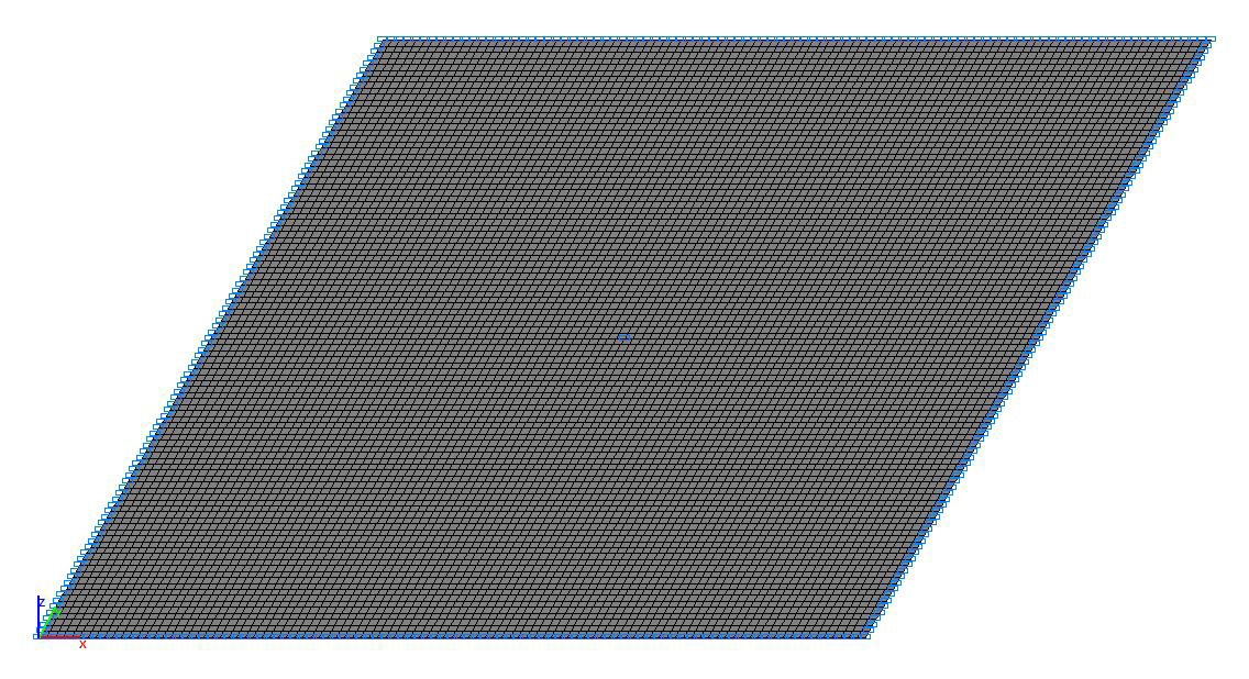
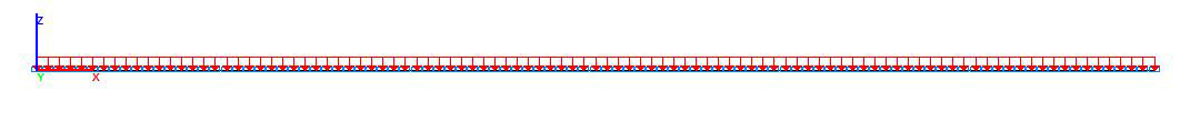
Design model
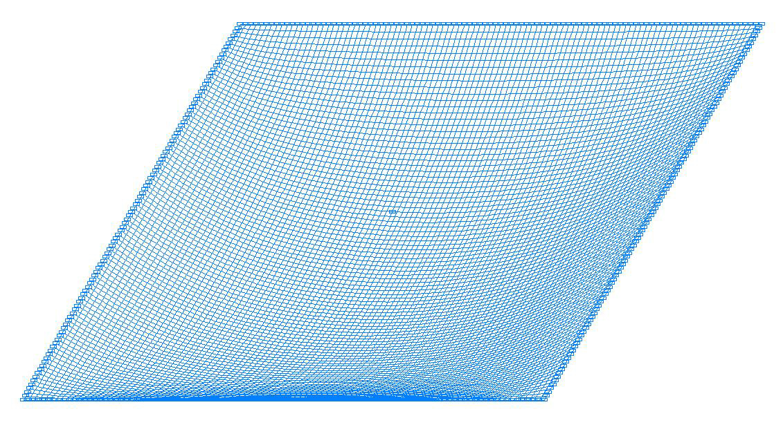
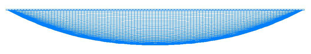
Deformed model
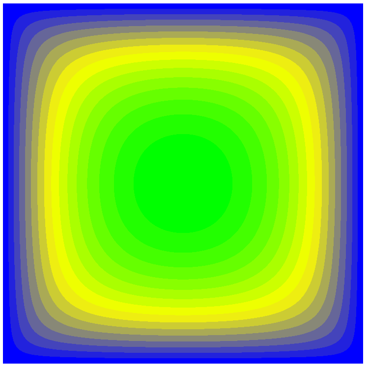
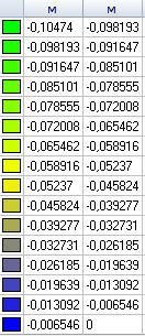
Values of transverse displacements w (m)
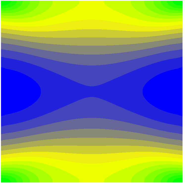
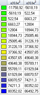
Values of longitudinal stresses Nx (kN/m2)
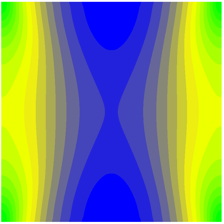
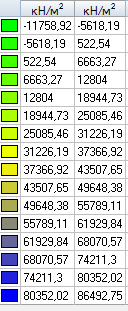
Values of longitudinal stresses Ny (kN/m2)
Comparison of solutions:
|
Parameter |
Theory |
SCAD |
Deviation, % |
|
Transverse displacement in the center of the plate w, m |
0.1050 (0.1067) |
0.1047 |
0.29 (1.87) |
|
Longitudinal stress in the center of the plate Nx, kN/m2 |
74963 (75830) |
74480 |
0.64 (1,7) |
|
Longitudinal stress in the center of the plate Ny, kN/m2 |
74963 (75830) |
74480 |
0.64 (1,7) |
The values of the approximate Hencky solution for the Karman theory are given without brackets;
The values of the refined Levy solution for the Karman theory are given in brackets
Notes: In the analytical approximate Hencky solution the transverse displacements w and the longitudinal stresses Nx and Ny for the center of the plate can be determined according to the following formulas (Poisson’s ratio ν = 0.3):
\[ w=0.285\cdot a\cdot \sqrt[3]{\frac{p}{E}\cdot \frac{a}{h}}; \quad N_{x} =N_{y} =3.4\cdot E\cdot \left( {\frac{w}{a}} \right)^{2}. \]