Simply Supported Flexible Circular Plate Subjected to a Uniformly Distributed Transverse Load
Objective: Determination of maximum displacements and longitudinal radial tangential stresses in a flexible circular plate simply supported along the contour and subjected to a uniformly distributed transverse load in the geometrically nonlinear formulation.
Initial data file: 7.7.spr
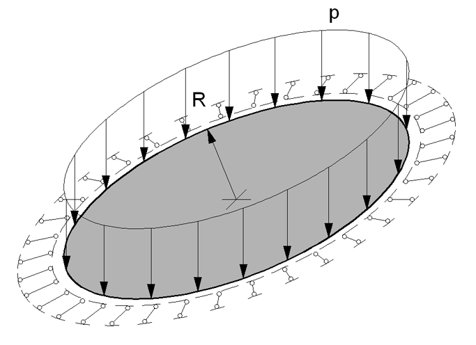
Problem formulation: The flexible circular isotropic plate of constant thickness is simply supported along the contour and subjected to the uniformly distributed transverse load p. Determine: the transverse displacements w and longitudinal radial tangential stresses Nr and Nt for the center of the plate.
References: S. Way, Bending of circular plates with large deflections, New York, ASME, v.56 N 8, 1934, p. 627-636.
H. Hencky, Uber den spannungsztand in kreisrunden platten mit verschwindender biegungssteifigkeit, Dresden, Zeitschrift für angewandte mathematic und physik, v.63, 1915, p. 311-317.
I.A. Birger, Ya.G. Panovko, Strength, Stability, Vibrations, Handbook in three volumes, Volume 1, Moscow, Mechanical engineering, 1968, p. 614
Initial data:
| E = 2.0·108 кПа | - elastic modulus of the plate material; |
| ν = 0.3 | - Poisson’s ratio; |
| h = 0.01 м | - thickness of the plate; |
| R = 5.0 м | - outer radius of the plate; |
| p = 10 кПа | - value of the uniformly distributed load. |
Finite element model: Design model – general type system. Elements of the plate - 8820 four-node shell elements taking into account the geometric nonlinearity of type 344 and 180 three-node shell elements taking into account the geometric nonlinearity of type 342. The spacing of the finite element mesh in the radial direction is 0.10 m and in the tangential direction is 2.0º. The direction of the output of internal forces is radial tangential. Boundary conditions are provided by imposing constraints in the directions of the degrees of freedom X, Y and Z along the external contour of the plate. The dimensional stability of the design model is provided by imposing a constraint in the node of the center of the plate in the UZ direction of the global coordinate system. The nonlinear loading was generated for the incremental-iterative method with a loading factor - 1, number of steps - 1, number of iterations - 100 for the linear loading p. Number of nodes in the design model – 9001.
Results in SCAD
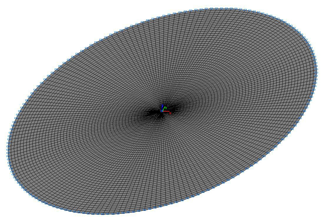

Design model
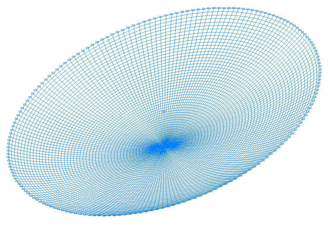
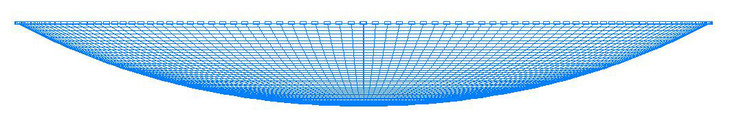
Deformed model
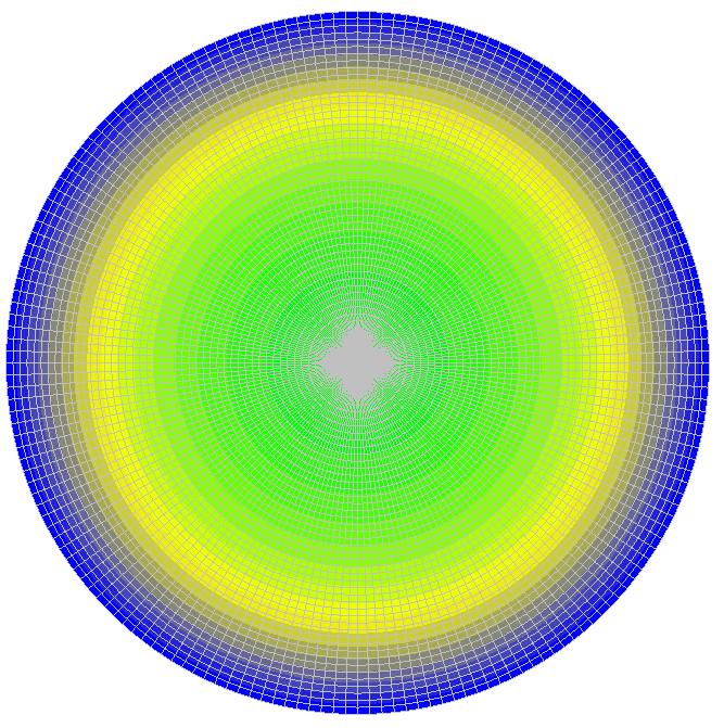
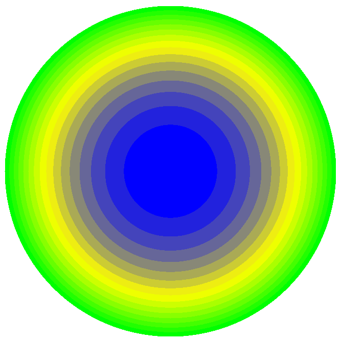
Values of transverse displacements w (m)
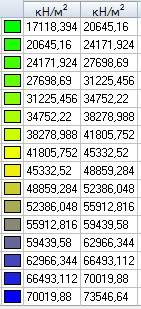
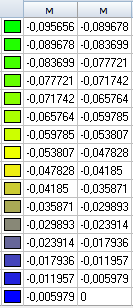
Values of longitudinal radial stresses Nr (kN/m2)
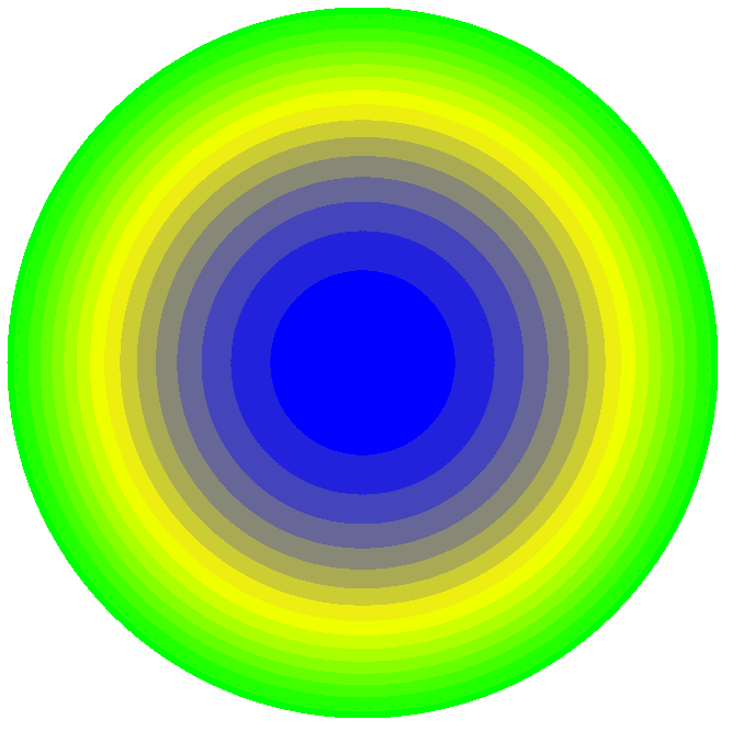
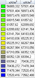
Values of longitudinal tangential stresses Nt (kN/m2)
Comparison of solutions:
|
Parameter |
Theory |
SCAD |
Deviation, % |
|---|---|---|---|
|
Transverse displacement in the center of the plate w, m |
0.0968 |
0.0957 |
1.14 |
|
Longitudinal radial stress in the center of the plate Nr, kN/m2 |
72316 |
73540 |
1.69 |
|
Longitudinal tangential stress in the center of the plate Nt, kN/m2 |
72316 |
73540 |
1.69 |
Notes: In the analytical approximate Hencky solution according to the Karman theory the transverse displacements w and the longitudinal radial tangential stresses Nr and Nt for the center of the plate can be determined according to the following formulas (Poisson’s ratio ν = 0.3):
\[ w=0.662\cdot R\cdot \sqrt[3]{\frac{p}{E}\cdot \frac{R}{h}}; \quad N_{r} =N_{t} =0.965\cdot E\cdot \left( {\frac{w}{R}} \right)^{2}. \]