Nearly Incompressible Thick-Walled Cylinder under Plane Deformation Subjected to Uniformly Distributed Internal Pressure

Objective: Check of the obtained values of radial displacements of the internal surface of a nearly incompressible thick-walled cylinder under plane deformation subjected to uniformly distributed internal pressure.
Initial data files:
|
File name |
Description |
|---|---|
|
Design model with the elements of type 42 for a material with Poisson's ratio 0.49, 0.499, 0.4999 |
|
|
Design model with the elements of type 44 for a material with Poisson's ratio 0.49, 0.499, 0.4999 |
|
|
Design model with the elements of type 45 for a material with Poisson's ratio 0.49, 0.499, 0.4999 |
|
|
Design model with the elements of type 50 for a material with Poisson's ratio 0.49, 0.499, 0.4999 |
|
|
Design model with the elements of type 36 for a material with Poisson's ratio 0.49, 0.499, 0.4999 |
|
|
Design model with the elements of type 37 for a material with Poisson's ratio 0.49, 0.499, 0.4999 |
Problem formulation: The nearly incompressible thick-walled cylinder is under plane deformation and is subjected to the uniformly distributed internal pressure p. Check the obtained values of the radial displacements of the internal surface u.
References: R. H. Macneal, R. L. Harder, A proposed standard set of problems to test finite element accuracy, North-Holland, Finite elements in analysis and design, 1, 1985, p. 3-20.
Initial data:
| E = 1000 kPa | - elastic modulus of the material of the thick-walled cylinder; |
| ν = 0.49; 0.499; 0.4999 | - Poisson’s ratio; |
| Ri = 3.00 m | - radius of the internal surface of the thick-walled cylinder; |
| Re = 9.00 m | - radius of the external surface of the thick-walled cylinder; |
| p = 1.0 kPa | - values of the uniformly distributed internal pressure. |
Finite element model: Design model – general type system. Six design models of a sector of the thick-walled cylinder with the thickness of 1.00 m and a central angle θ = 10° according to the symmetry conditions are considered:
Model 1 – 10 three-node shell elements of type 42 of unequal sizes with the spacing of the mesh in the radial direction 3.00 m, 3.50 m, 4.20 m, 5.20 m, 6.75 m, 9.00 m . Boundary conditions are provided by introducing 12 space truss bar elements of type 4 of high axial stiffness (EF = 106 kN) in the tangential direction (orthogonal to the lateral surfaces of the sector). Constraints in the directions of the degrees of freedom X, Y, Z are imposed on the support nodes of the bar elements. The dimensional stability is provided by imposing constraints on the lateral surfaces of the sector in the directions of the degrees of freedom Z, UZ. The load uniformly distributed along the line p = 1.0 kN/m is applied to the element on the internal surface of the cylinder. Number of nodes in the model – 24.
Model 2 – 5 four-node shell elements of type 44 of unequal sizes with the spacing of the mesh in the radial direction 3.00 m, 3.50 m, 4.20 m, 5.20 m, 6.75 m, 9.00 m . Boundary conditions are provided by introducing 12 space truss bar elements of type 4 of high axial stiffness (EF = 106 kN) in the tangential direction (orthogonal to the lateral surfaces of the sector). Constraints in the directions of the degrees of freedom X, Y, Z are imposed on the support nodes of the bar elements. The dimensional stability is provided by imposing constraints on the lateral surfaces of the sector in the directions of the degrees of freedom Z, UZ. The load uniformly distributed along the line p = 1.0 kN/m is applied to the element on the internal surface of the cylinder. Number of nodes in the model – 24.
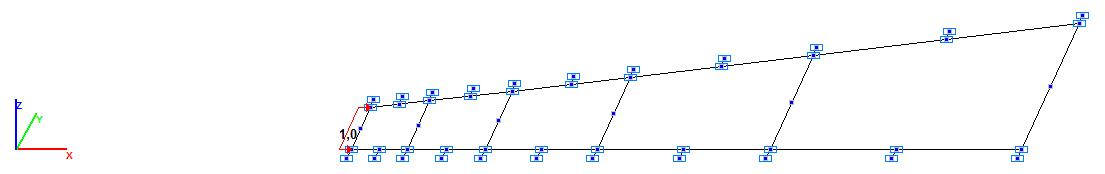
Model 3 – 10 six-node shell elements of type 45 of unequal sizes with the spacing of the mesh in the radial direction 3.00 m, 3.50 m, 4.20 m, 5.20 m, 6.75 m, 9.00 m. Boundary conditions are provided by introducing 22 space truss bar elements of type 4 of high axial stiffness (EF = 106 kN) in the tangential direction (orthogonal to the lateral surfaces of the sector). Constraints in the directions of the degrees of freedom X, Y, Z are imposed on the support nodes of the bar elements. The dimensional stability is provided by imposing constraints on the lateral surfaces of the sector in the directions of the degrees of freedom Z, UZ. The load uniformly distributed along the line p = 1.0 kN/m is applied to the element on the internal surface of the cylinder. Number of nodes in the model – 55.
Model 4 – 5 eight-node shell elements of type 50 of unequal sizes with the spacing of the mesh in the radial direction 3.00 m, 3.50 m, 4.20 m, 5.20 m, 6.75 m, 9.00 m. Boundary conditions are provided by introducing 22 space truss bar elements of type 4 of high axial stiffness (EF = 106 kN) in the tangential direction (orthogonal to the lateral surfaces of the sector). Constraints in the directions of the degrees of freedom X, Y, Z are imposed on the support nodes of the bar elements. The dimensional stability is provided by imposing constraints on the lateral surfaces of the sector in the directions of the degrees of freedom Z, UZ. The load uniformly distributed along the line p = 1.0 kN/m is applied to the element on the internal surface of the cylinder. Number of nodes in the model – 50.
Model 5 – 5 eight-node isoparametric solid elements of type 36 of unequal sizes with the spacing of the mesh in the radial direction 3.00 m, 3.50 m, 4.20 m, 5.20 m, 6.75 m, 9.00 m. Boundary conditions are provided by introducing 24 space truss bar elements of type 4 of high axial stiffness (EF = 106 kN) in the tangential direction (orthogonal to the lateral surfaces of the sector). Constraints in the directions of the degrees of freedom X, Y, Z are imposed on the support nodes of the bar elements. The dimensional stability is provided by imposing constraints on the lateral surfaces of the sector in the direction of the degree of freedom Z. The load uniformly distributed over the face p = 1.0 kN/m2 is applied to the element on the internal surface of the cylinder. Number of nodes in the model – 50.
Model 6 – 5 twenty-node isoparametric solid elements of type 37 of unequal sizes with the spacing of the mesh in the radial direction 3.00 m, 3.50 m, 4.20 m, 5.20 m, 6.75 m, 9.00 m. Boundary conditions are provided by introducing 56 space truss bar elements of type 4 of high axial stiffness (EF = 106 kN) in the tangential direction (orthogonal to the lateral surfaces of the sector). Constraints in the directions of the degrees of freedom X, Y, Z are imposed on the support nodes of the bar elements. The dimensional stability is provided by imposing constraints on the lateral surfaces of the sector in the direction of the degree of freedom Z. The load uniformly distributed over the face p = 1.0 kN/m2 is applied to the element on the internal surface of the cylinder. Number of nodes in the model – 124.
Results in SCAD
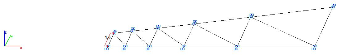
Model 1. Design model
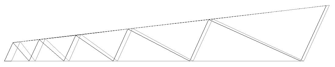
Model 1. Deformed model
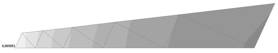
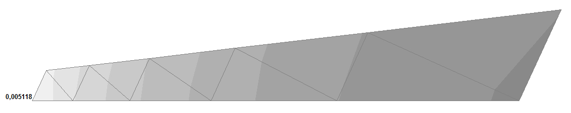

Model 1. Values of the displacements in the direction of the X axis of the global coordinate system (m) for the materials of the thick-walled cylinder with Poisson's ratio 0.49; 0.499; 0.4999
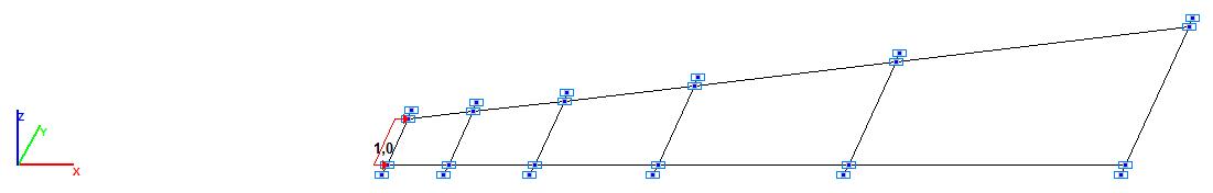
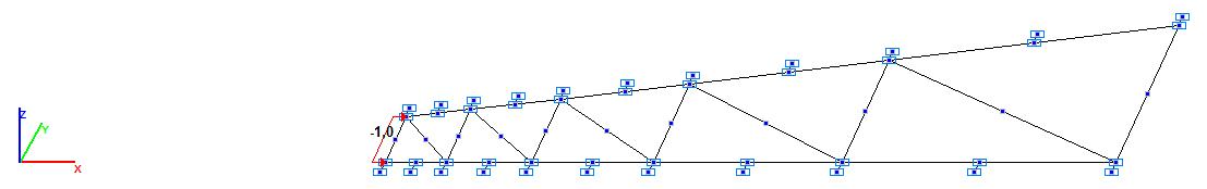
Model 2. Design model
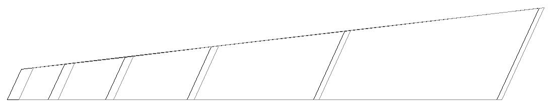
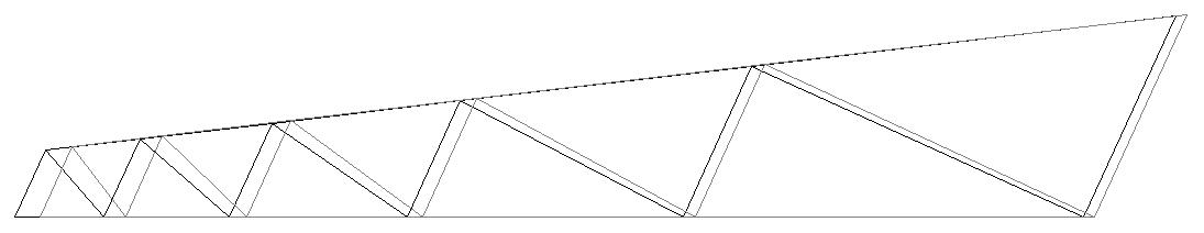
Model 2. Deformed model
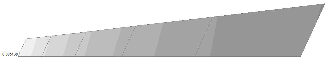
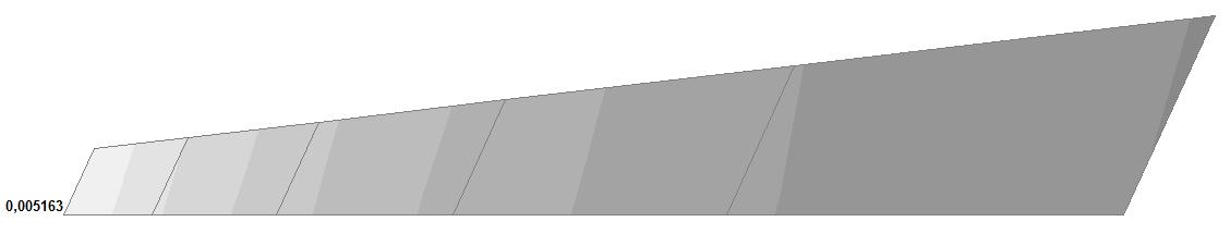
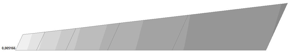
Model 2. Values of the displacements in the direction of the X axis of the global coordinate system (m) for the materials of the thick-walled cylinder with Poisson's ratio 0.49; 0.499; 0.4999
Model 3. Design model
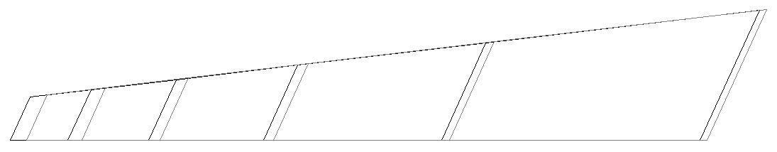
Model 3. Deformed model
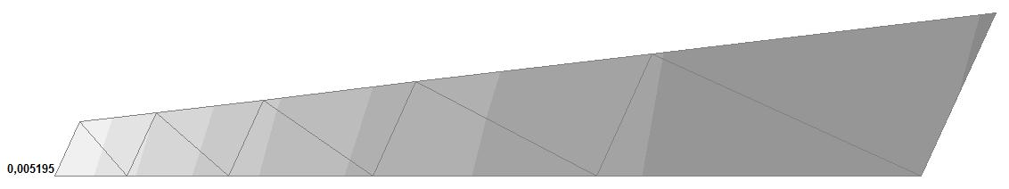
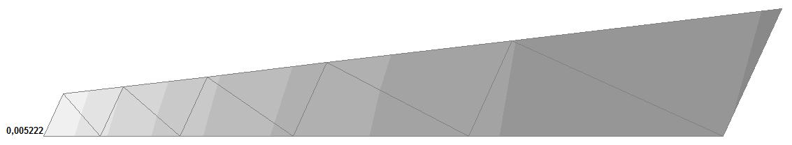
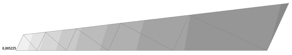
Model 3. Values of the displacements in the direction of the X axis of the global coordinate system (m) for the materials of the thick-walled cylinder with Poisson's ratio 0.49; 0.499; 0.4999
Model 3. Design model
Model 4. Deformed model
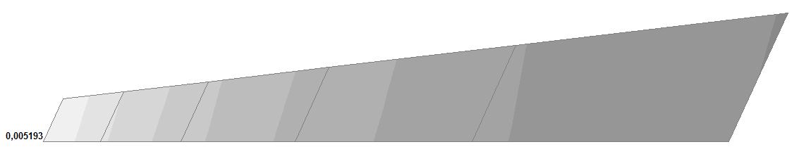

Model 4. Values of the displacements in the direction of the X axis of the global coordinate system (m) for the materials of the thick-walled cylinder with Poisson's ratio 0.49; 0.499; 0.4999
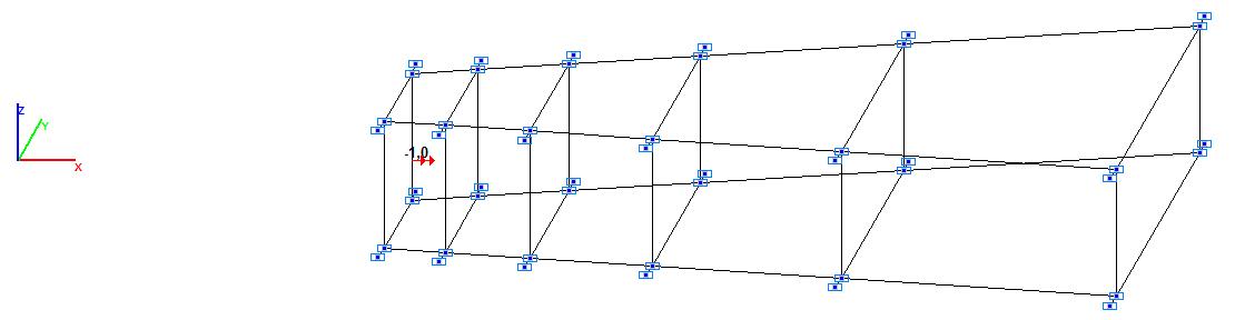
Model 5.Design model
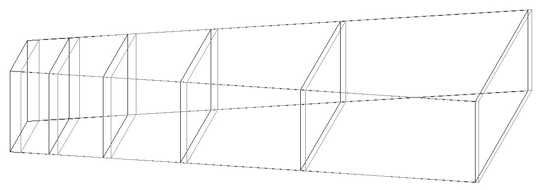
Model 5. Deformed model
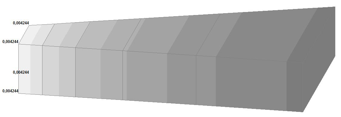
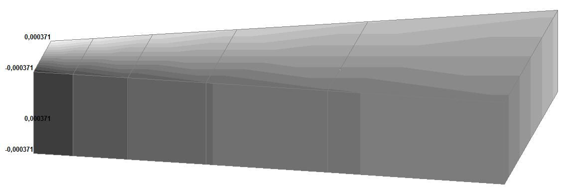

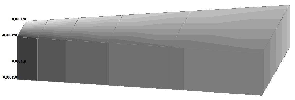
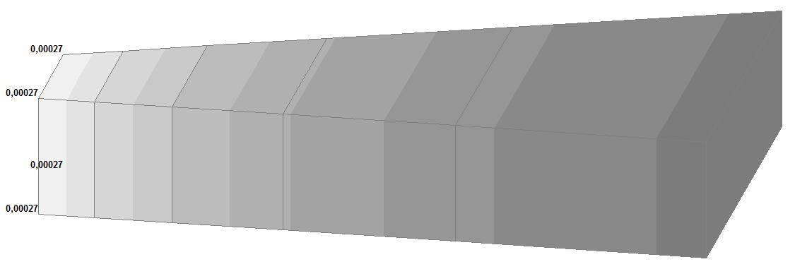
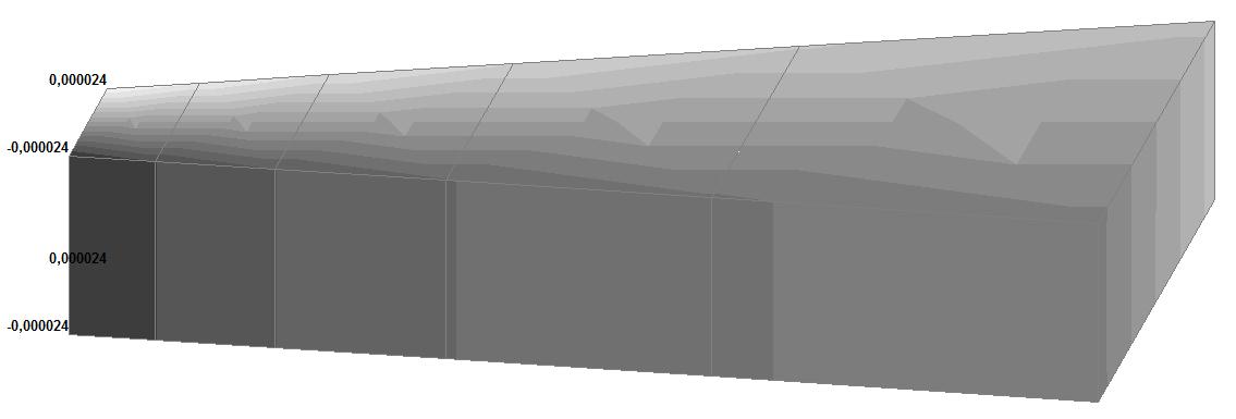
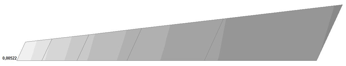
Model 5. Values of the displacements in the directions of the X and Y axes of the global coordinate system (m, m) for the materials of the thick-walled cylinder with Poisson's ratio 0.49; 0.499; 0.4999
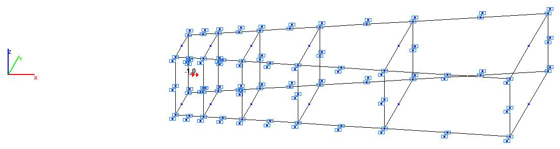
Model 6.Design model
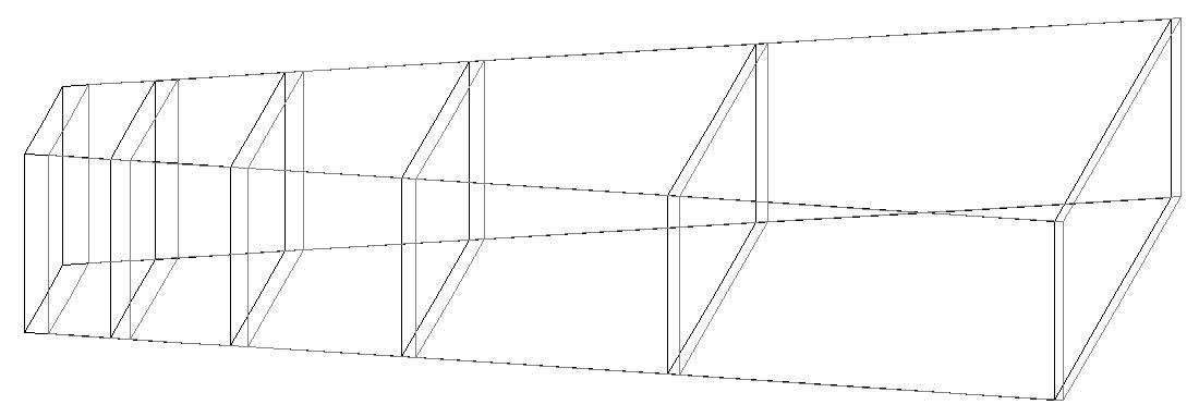
Model 6. Deformed model
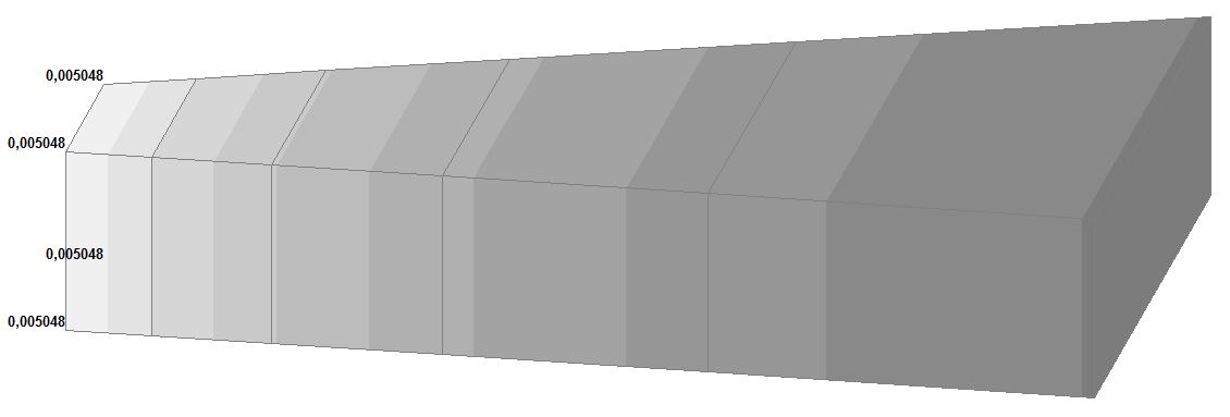
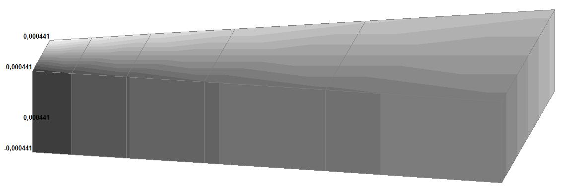
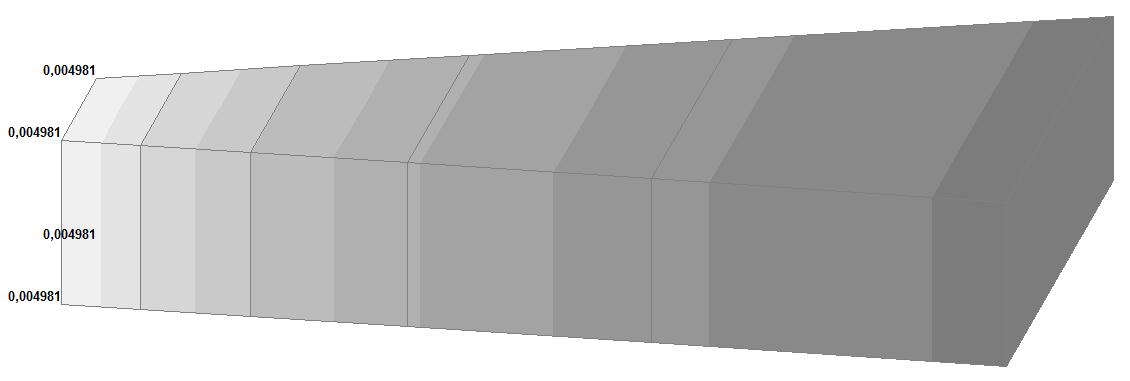
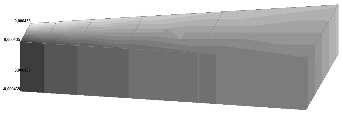
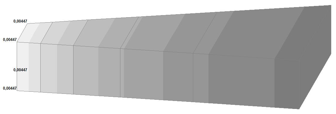
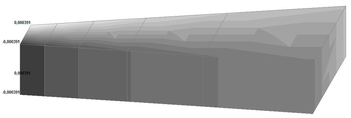
Model 6. Values of the displacements in the directions of the X and Y axes of the global coordinate system (m, m) for the materials of the thick-walled cylinder with Poisson's ratio 0.49; 0.499; 0.4999
Comparison of solutions:
Radial displacements of the internal surface of the thick-walled cylinder u (m) for the materials with Poisson's ratios 0.49; 0.499; 0.4999
|
Model |
Poisson’s ratio |
Theory |
SCAD |
Deviation, % |
|---|---|---|---|---|
|
1 (Member type 42) |
0.49 |
0.005040 |
0.005093 |
1.05 |
|
0.499 |
0.005060 |
0.005118 |
1.15 |
|
|
0.4999 |
0.005062 |
0.005121 |
1.17 |
|
|
2 (Member type 44) |
0.49 |
0.005040 |
0.005138 |
1.94 |
|
0.499 |
0.005060 |
0.005163 |
2.04 |
|
|
0.4999 |
0.005062 |
0.005166 |
2.05 |
|
|
3 (Member type 45) |
0.49 |
0.005040 |
0.005195 |
3.08 |
|
0.499 |
0.005060 |
0.005222 |
3.20 |
|
|
0.4999 |
0.005062 |
0.005225 |
3.22 |
|
|
4 (Member type 50) |
0.49 |
0.005040 |
0.005193 |
3.04 |
|
0.499 |
0.005060 |
0.005222 |
3.20 |
|
|
0.4999 |
0.005062 |
0.005223 |
3.18 |
|
|
5 (Member type 36) |
0.49 |
0.005040 |
√(0.0042442 + + 0.0003712) = = 0.004260 |
15.48 |
|
0.499 |
0.005060 |
√(0.0018112 + + 0.0001582) = = 0.001818 |
64.07 |
|
|
0.4999 |
0.005062 |
√(0.0002702 + + 0.0000242) = = 0.000271 |
94.65 |
|
|
6 (Member type 37) |
0.49 |
0.005040 |
√(0.0050482 + + 0.0004412) = = 0.005067 |
0.54 |
|
0.499 |
0.005060 |
√(0.0049812 + + 0.0004352) = = 0.005000 |
1.19 |
|
|
0.4999 |
0.005062 |
√(0.0044702 + + 0.0003912) = = 0.004487 |
11.36 |
Notes: In the analytical solution the radial displacements of the internal surface of the nearly incompressible thick-walled cylinder under the plane deformation u from the uniformly distributed internal pressure are determined according to the following formulas:
\[ u=\frac{\left( {1+\nu } \right)\cdot p\cdot R_{i}^{2}}{E\cdot \left( {R_{e} ^{2}-R_{i}^{2}} \right)}\cdot \left[ {\frac{R_{e}^{2}}{R_{i} }+\left( {1-2\cdot \nu } \right)\cdot R_{i} } \right]. \]