Free Hemispherical Shell with a Circular Pole Hole Subjected to Two Orthogonal Pairs of Mutually Balanced Radial Tensile and Compressive Forces Applied at the Equator

Objective: Check of the obtained values of the transverse displacements of a free hemispherical shell with a circular pole hole in the direction of action of two orthogonal pairs of mutually balanced radial tensile and compressive forces applied at the equator.
Initial data files:
|
File name |
Description |
|---|---|
|
Design model with the elements of type 42 for meshes 2x2, 4x4, 8x8, 16x16, 32x32 |
|
|
Design model with the elements of type 44 for meshes 2x2, 4x4, 8x8, 16x16, 32x32 |
|
|
Design model with the elements of type 45 for meshes 2x2, 4x4, 8x8, 16x16, 32x32 |
|
|
Design model with the elements of type 50 for meshes 2x2, 4x4, 8x8, 16x16, 32x32 |
|
|
Design model with the elements of type 36 for meshes 2x2, 4x4, 8x8, 16x16, 32x32, 64x64, 128x128, 256x256, 512x512 |
|
|
Design model with the elements of type 37 for meshes 2x2, 4x4, 8x8, 16x16, 32x32, 64x64, 128x128 |
Problem formulation: The free hemispherical shell with a circular pole hole is subjected to two orthogonal pairs of mutually balanced radial tensile and compressive forces F applied at the equator. Check the obtained values of the transverse displacements of the free hemispherical shell wFX and wFY in the direction of the action of forces applied at the equator.
References: R. H. Macneal, R. L. Harder, A proposed standard set of problems to test finite element accuracy, North-Holland, Finite elements in analysis and design, 1, 1985, p. 3-20.
L. S. D. Morley, A. J. Morris, Conflict between finite elements and shell theory, London, Royal aircraft establishment report, 1978.
Initial data:
| E = 6.825·107 kPa | - elastic modulus of the material of the hemispherical shell; |
| ν = 0.30 | - Poisson’s ratio; |
| R = 10.00 m | - radius of the midsurface of the hemispherical shell; |
| 2·θ = 2·18° | - central angle of the surface of the circular hole of the hemispherical shell; |
| h = 0.04 m | - thickness of the hemispherical shell; |
| FX = + 2.0 kN | - values of the concentrated radial tensile forces applied at the equator of the hemispherical shell; |
| FY = – 2.0 кН | - values of the concentrated radial compressive forces applied at the equator of the hemispherical shell. |
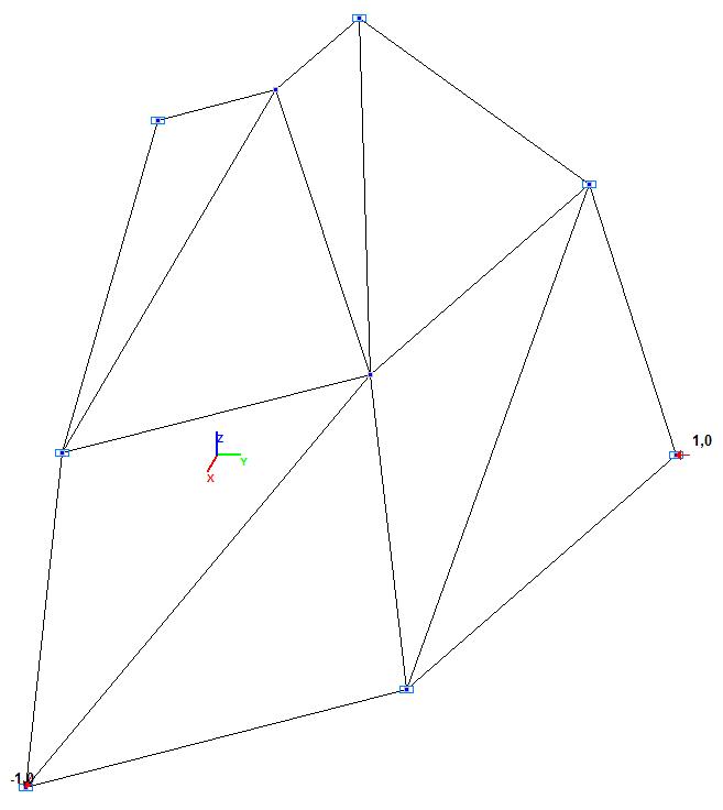
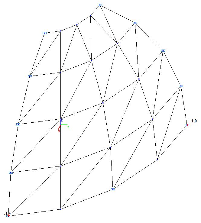
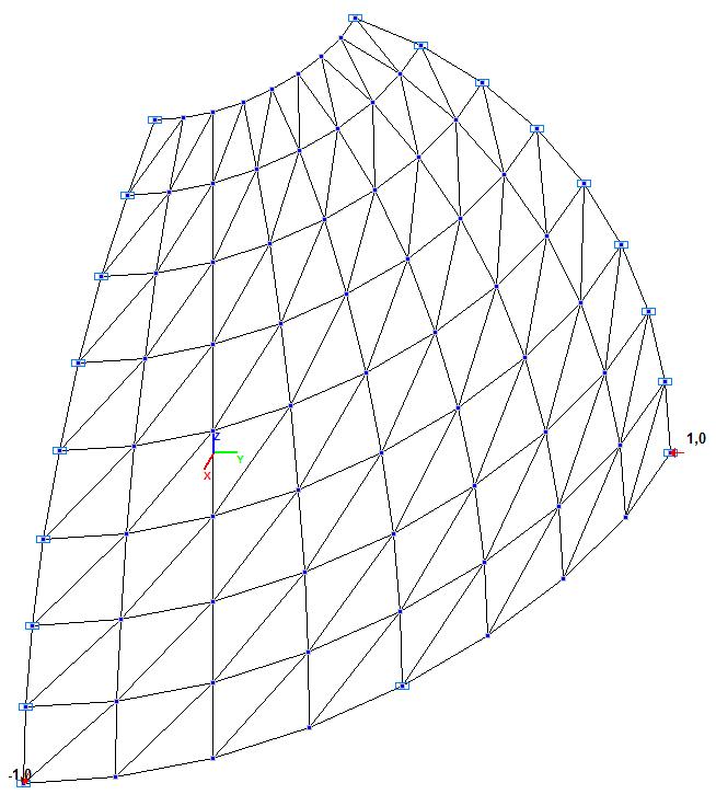
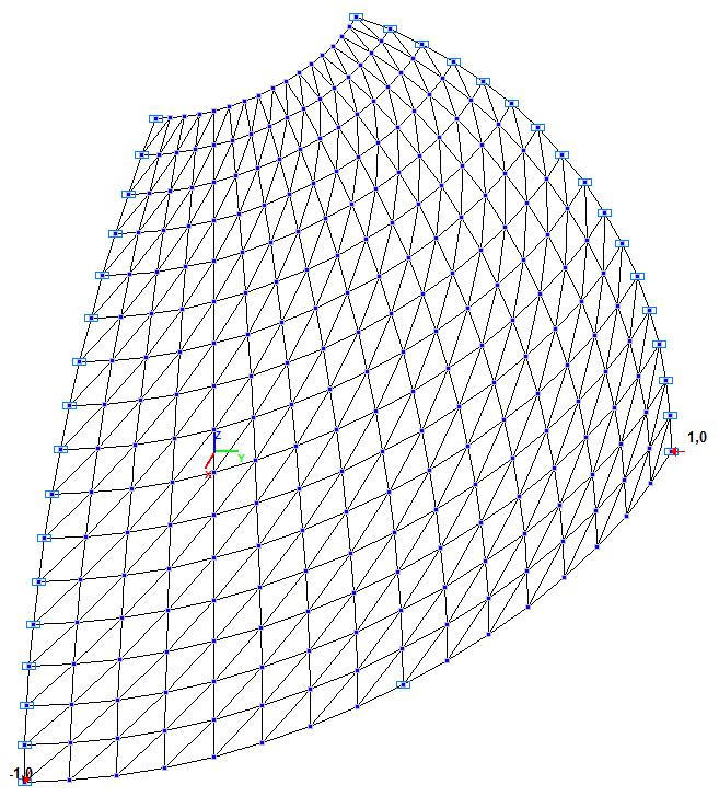
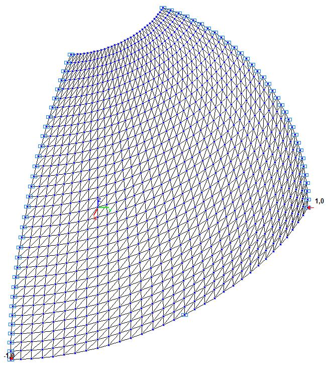
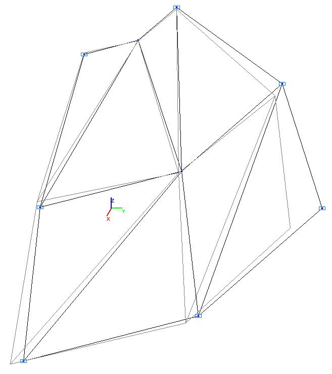
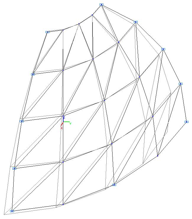
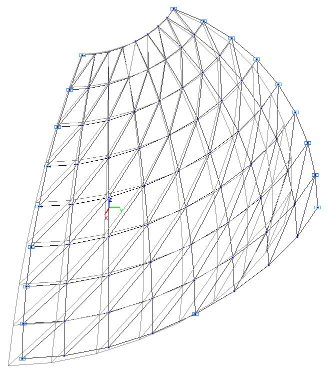
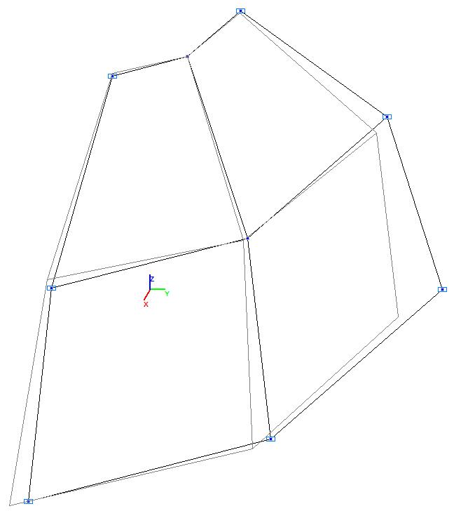
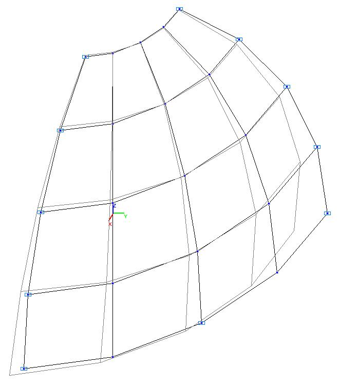
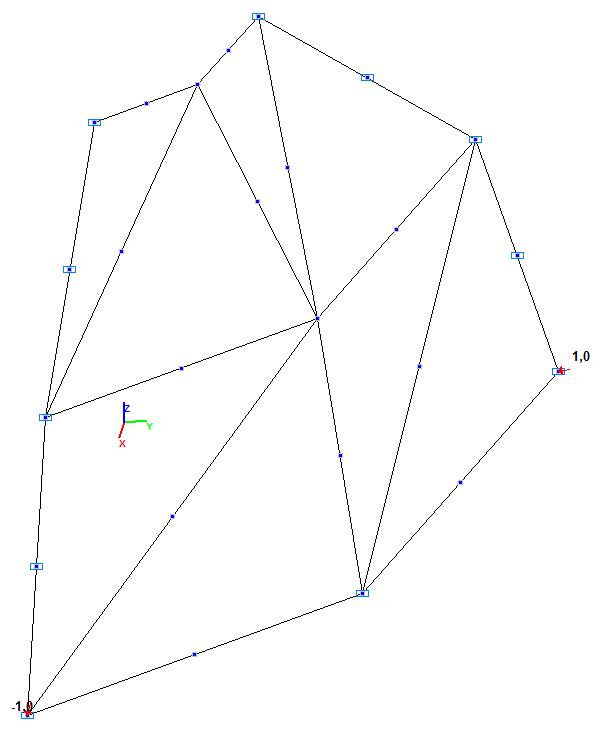
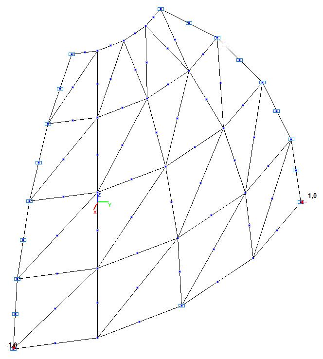
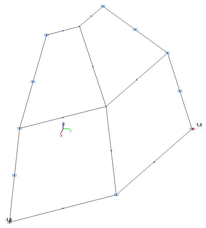
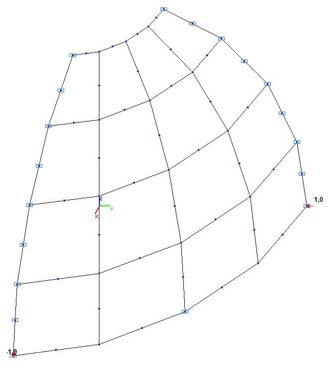
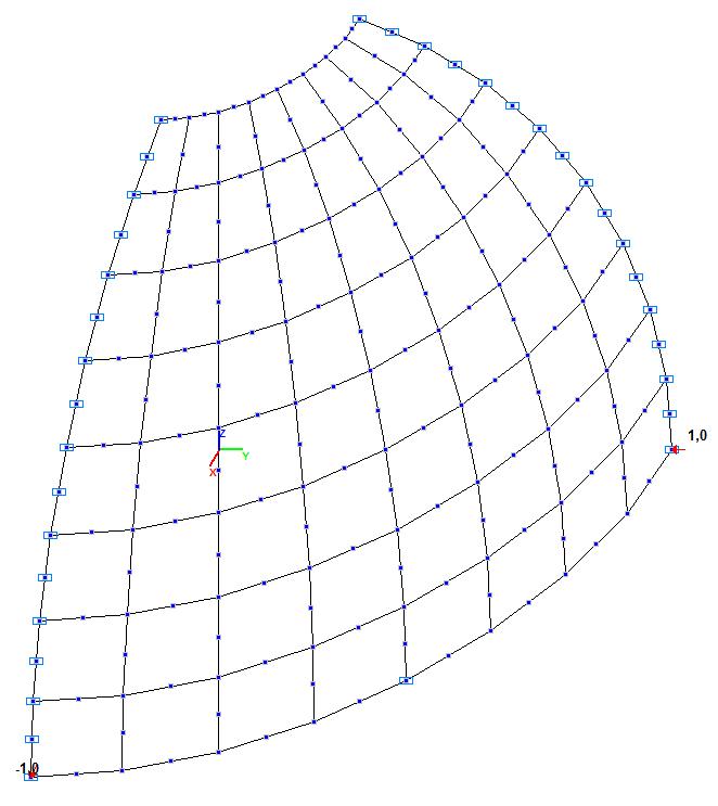
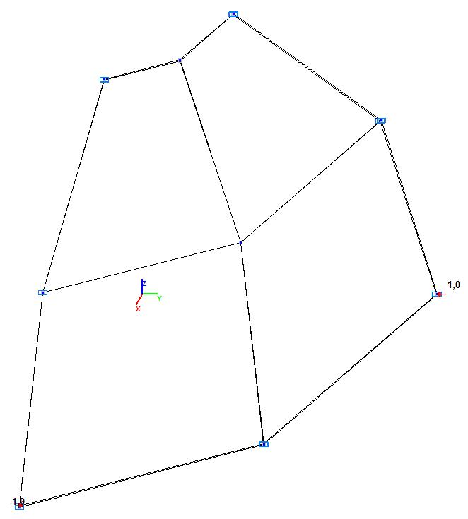
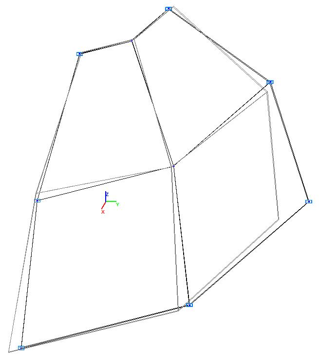
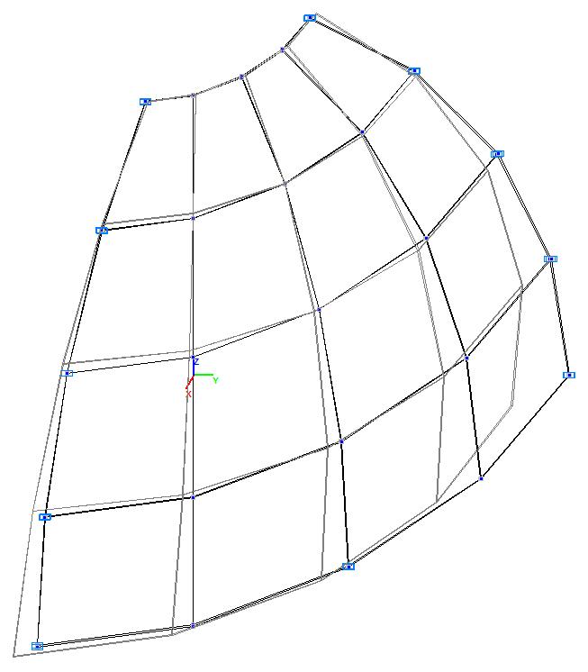
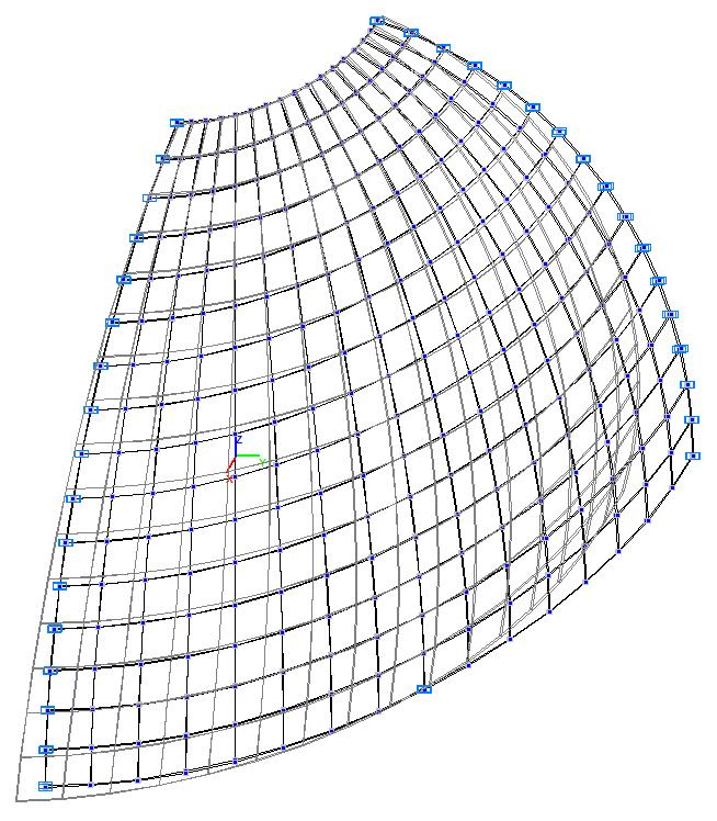
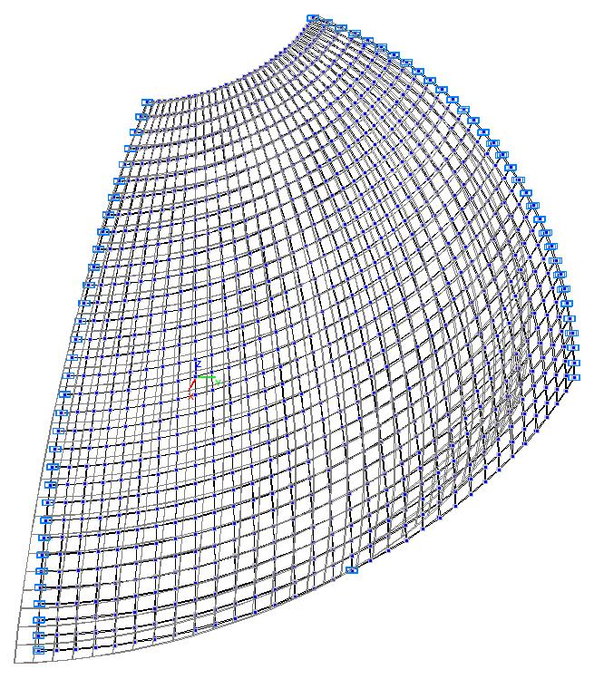
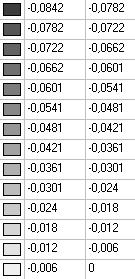
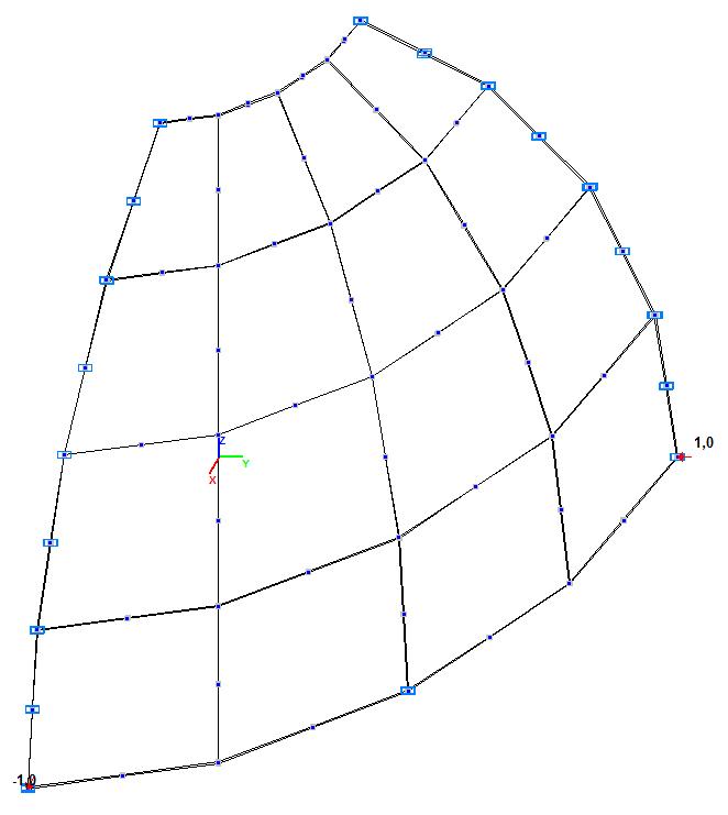
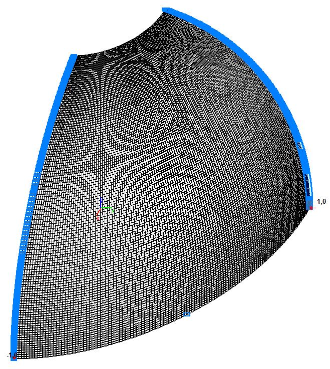
Finite element model: Design model – general type system. Six design models of a quarter of the hemispherical shell according to the symmetry conditions are considered:
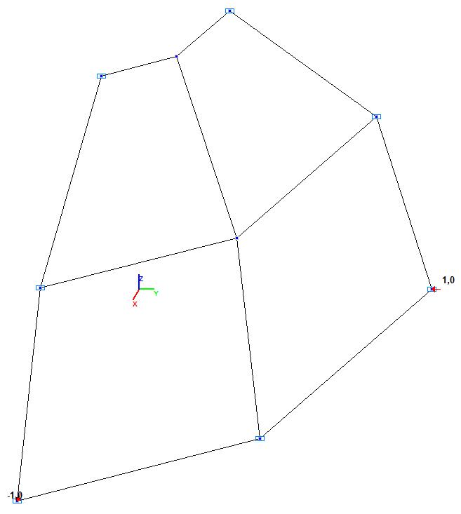
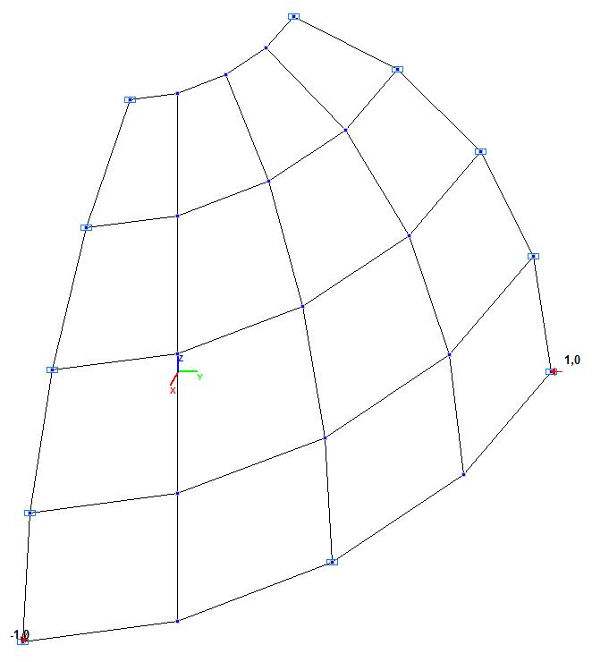
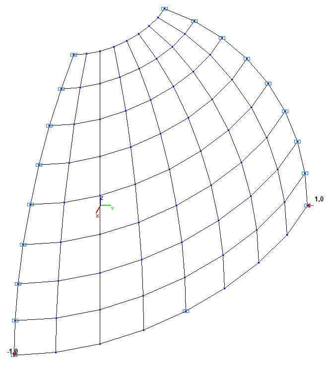
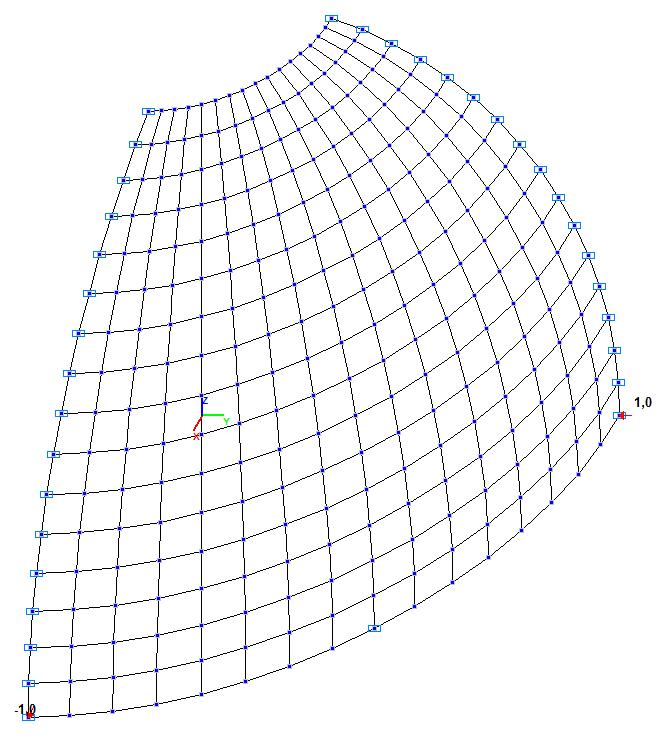
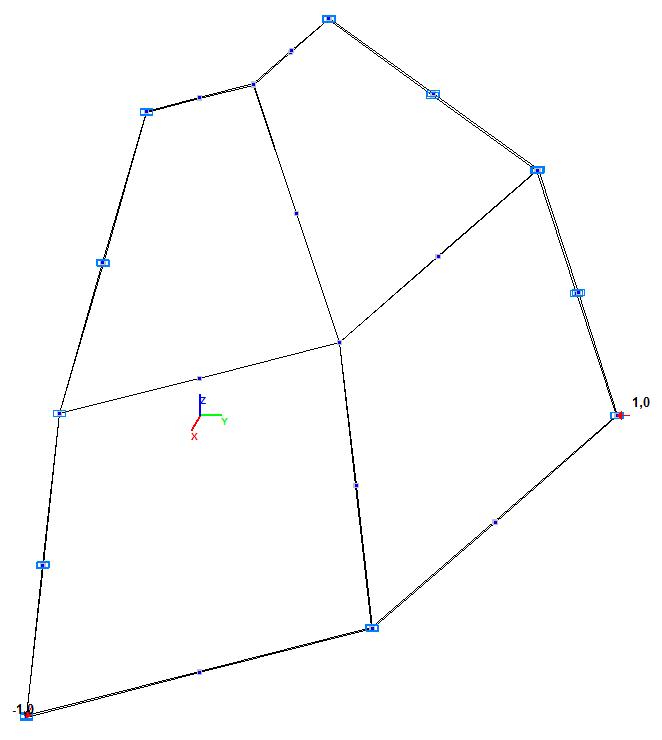
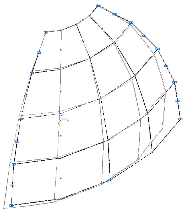
Model 1 – 8, 32, 128, 512, 2048 three-node shell elements of type 42 with a regular mesh 2x2, 4x4, 8x8, 16x16, 32x32. Boundary conditions and the dimensional stability are provided by imposing constraints according to the symmetry conditions. Number of nodes in the model – 9, 25, 81, 289, 1089.
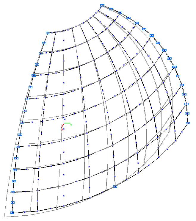
Model 2 – 4, 16, 64, 256, 1024 four-node shell elements of type 44 with a regular mesh 2x2, 4x4, 8x8, 16x16, 32x32. Boundary conditions and the dimensional stability are provided by imposing constraints according to the symmetry conditions. Number of nodes in the model – 9, 25, 81, 289,1089.
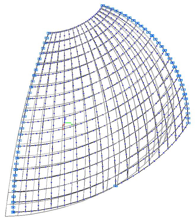
Model 3 – 8, 32, 128, 512, 2048 six-node shell elements of type 45 with a regular mesh 2x2, 4x4, 8x8, 16x16, 32x32. Boundary conditions and the dimensional stability are provided by imposing constraints according to the symmetry conditions. Number of nodes in the model – 25, 81, 289, 1089, 4225.
Model 4 – 4, 16, 64, 256, 1024 eight- node shell elements of type 50 with a regular mesh 2x2, 4x4, 8x8, 16x16, 32x32. Boundary conditions and the dimensional stability are provided by imposing constraints according to the symmetry conditions. Number of nodes in the model – 21, 65, 225, 833, 3201.
Model 5 – 4, 16, 64, 256, 1024, 4096, 16384, 65536, 262144 eight-node isoparametric solid elements of type 36 with a regular mesh 2x2x1, 4x4x1, 8x8x1, 16x16x1, 32x32x1, 64x64x1, 128x128x1, 256x256x1, 512x512x1. Boundary conditions and the dimensional stability are provided by imposing constraints according to the symmetry conditions. Number of nodes in the model – 18, 50, 162, 578, 2178, 8450, 33282, 132149, 526338.
Model 6 – 4, 16, 64, 256, 1024, 4096, 16384 twenty-node isoparametric solid elements of type 37 with a regular mesh 2x2x1, 4x4x1, 8x8x1, 16x16x1, 32x32x1, 64x64x1, 128x128x1. Boundary conditions and the dimensional stability are provided by imposing constraints according to the symmetry conditions. Number of nodes in the model – 51, 155, 531, 1955, 7491, 29315, 115971.
Results in SCAD
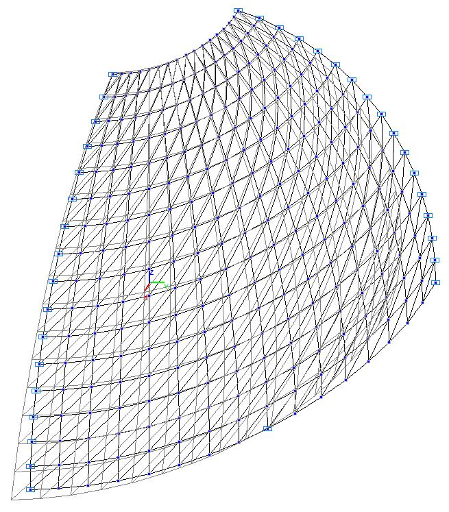
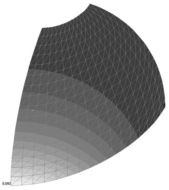
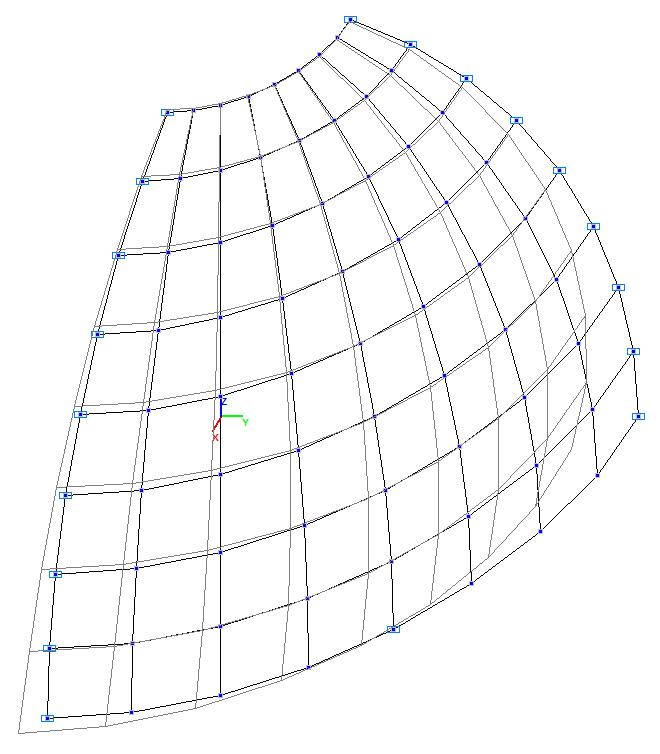
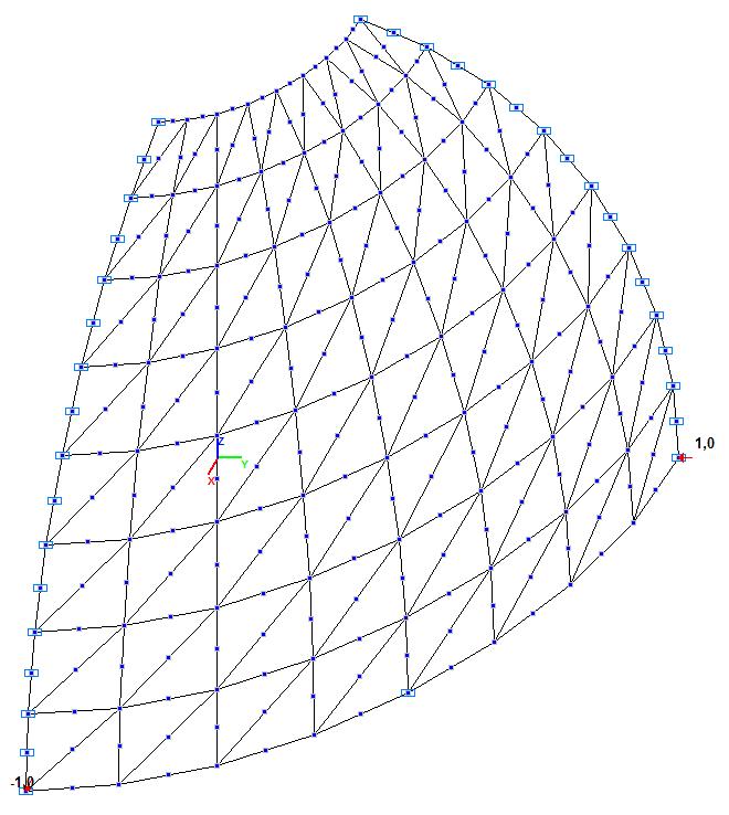
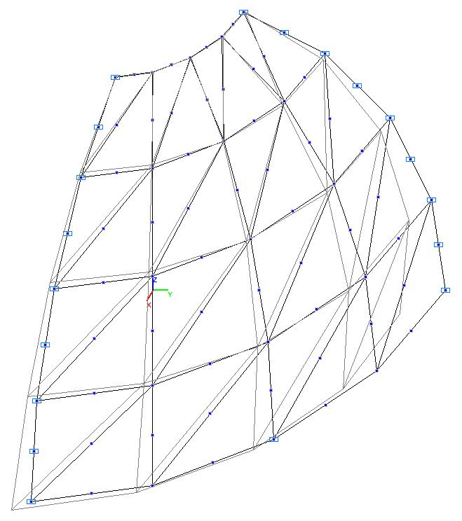
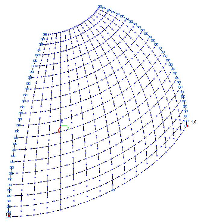
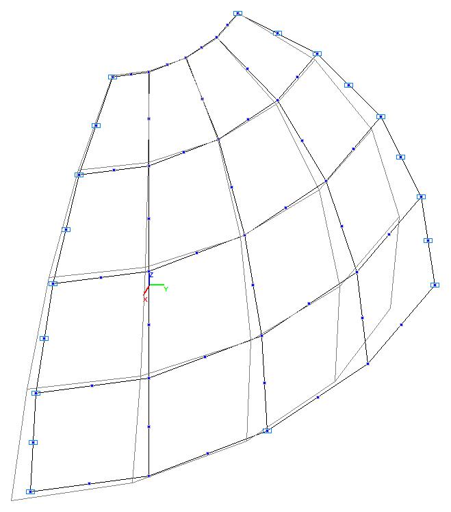
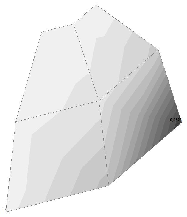
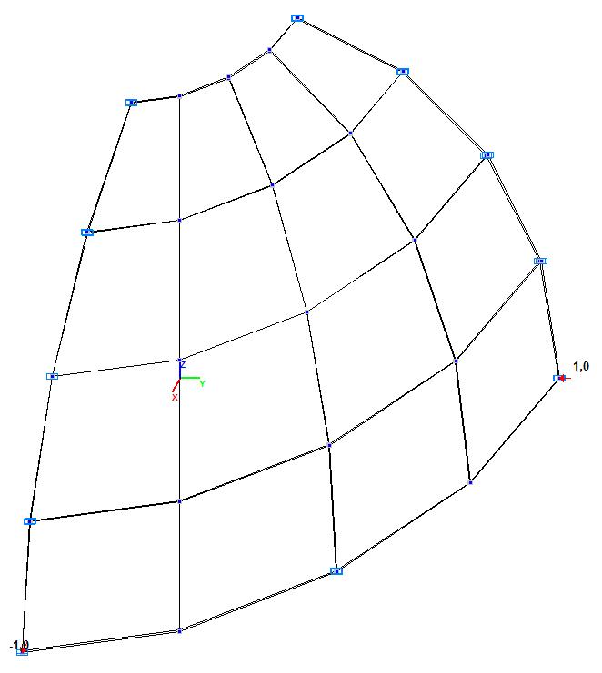
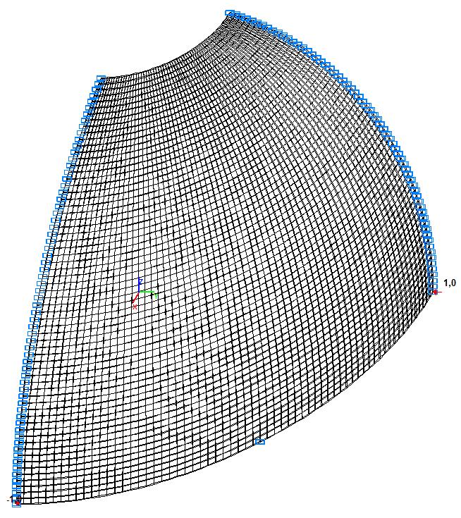
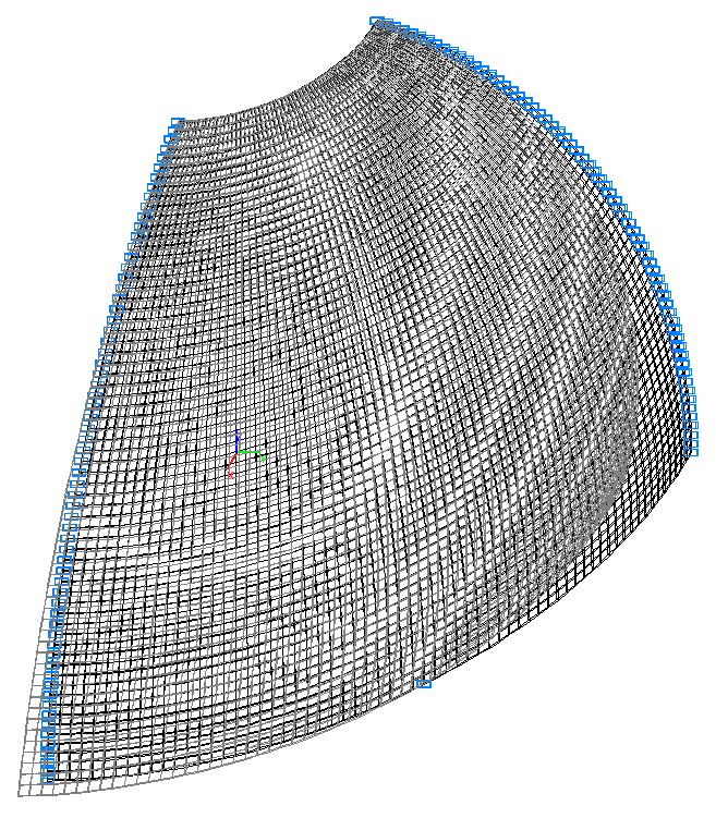
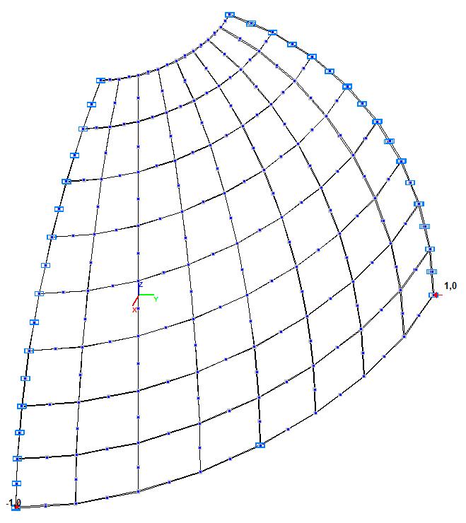
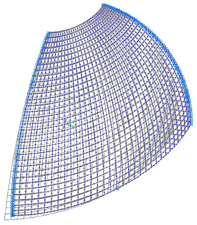
Model 1. Design model
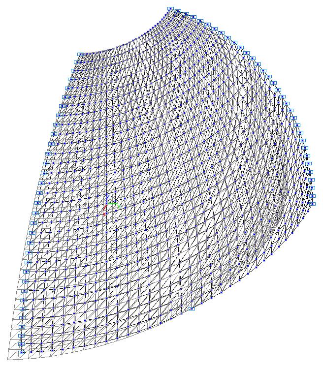
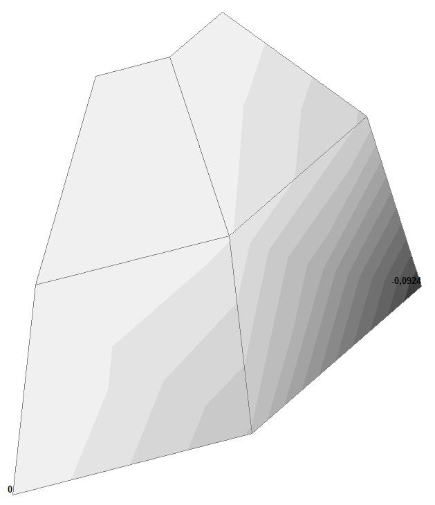
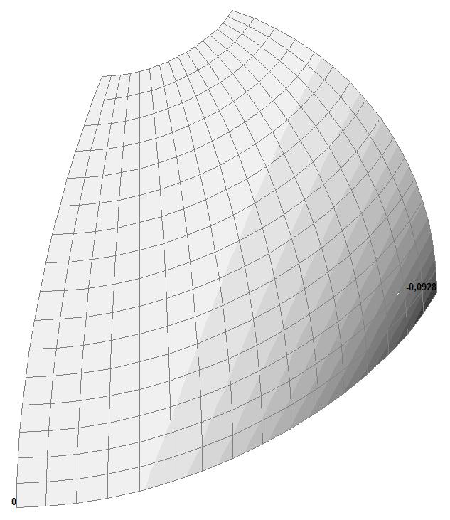
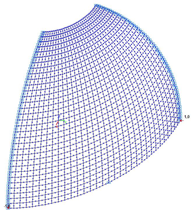
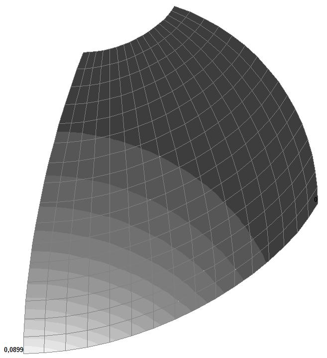
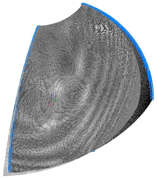
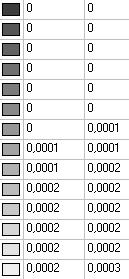
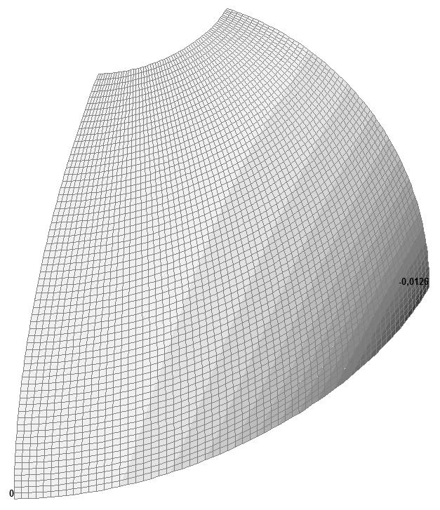
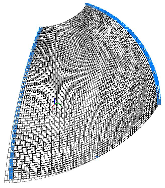
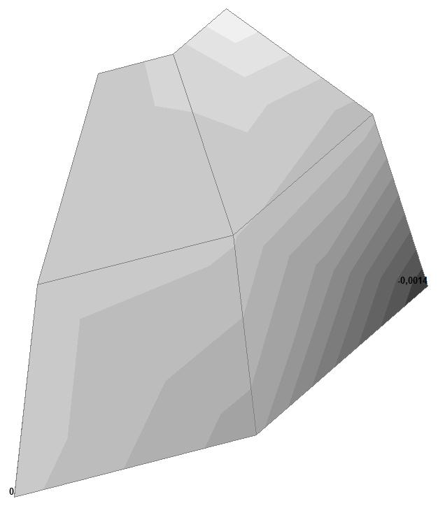
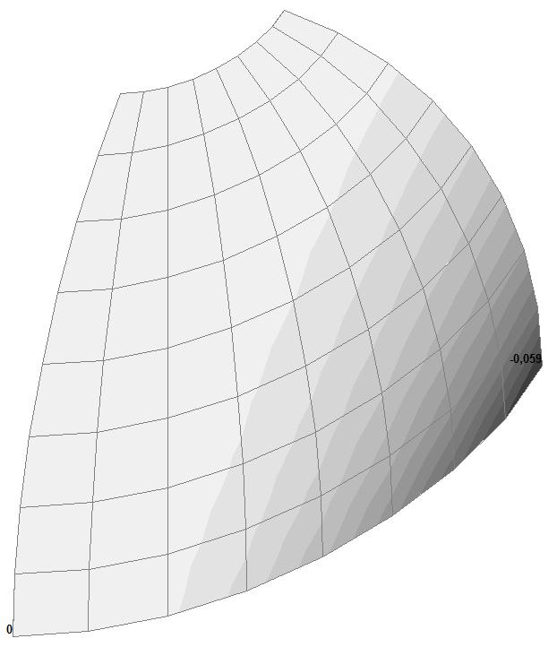
Model 1. Deformed model
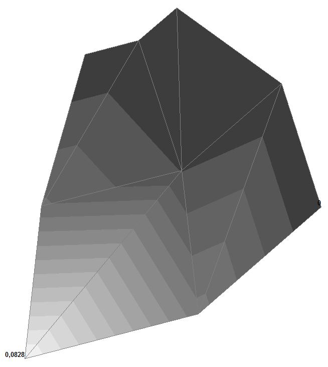
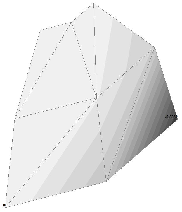

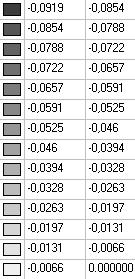


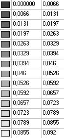

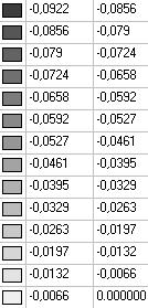
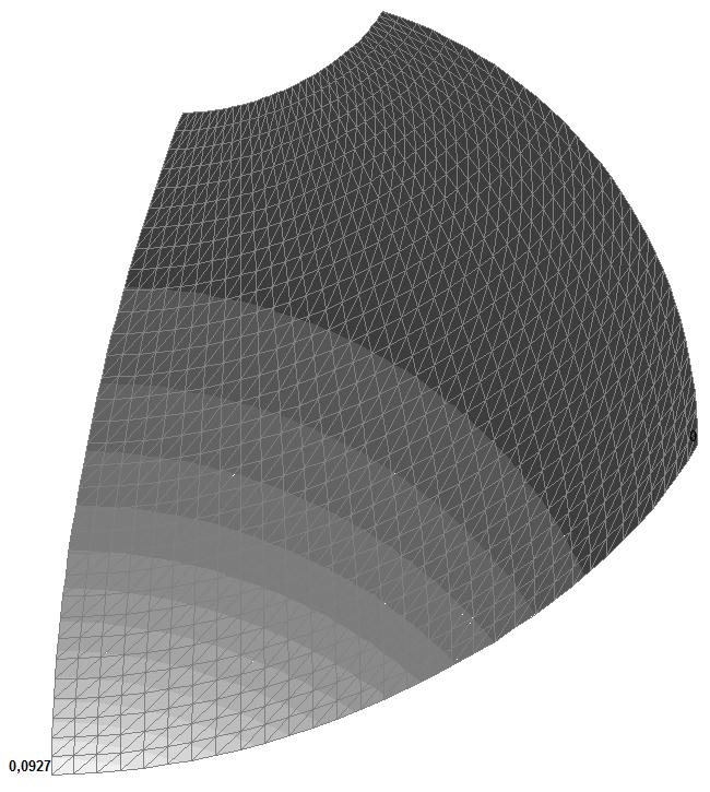
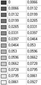

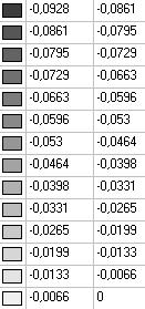
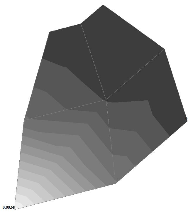
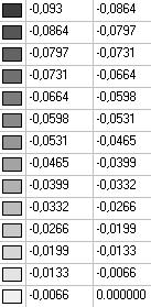
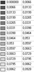
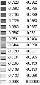
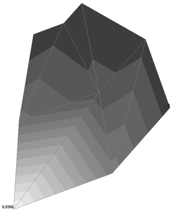
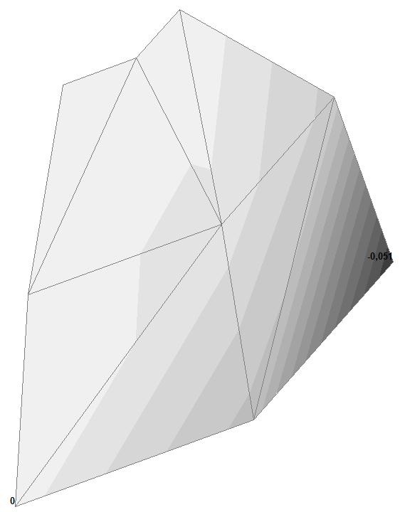
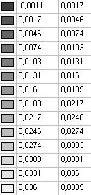
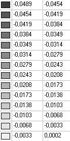
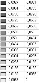
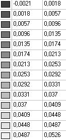
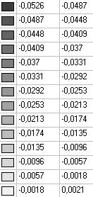
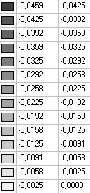
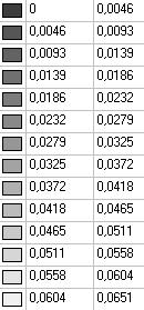
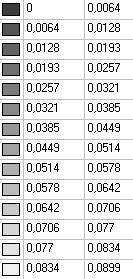
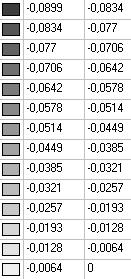
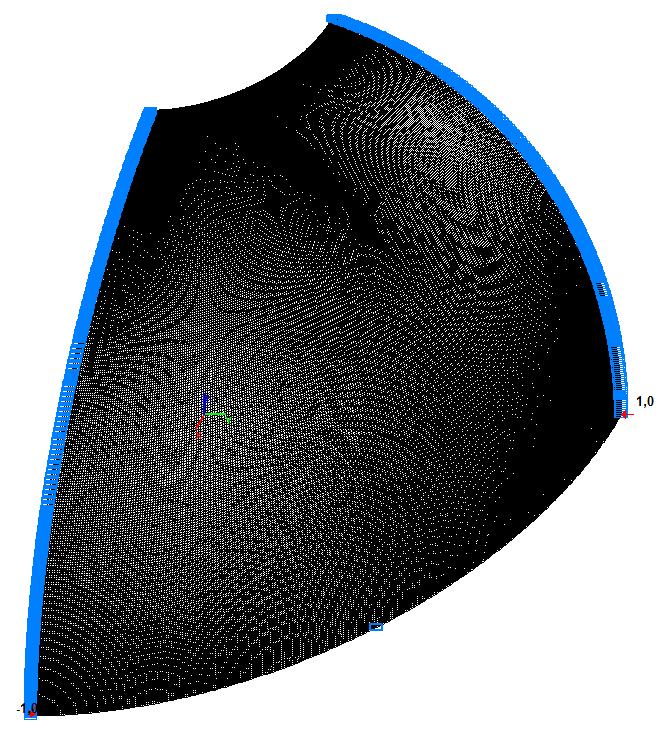
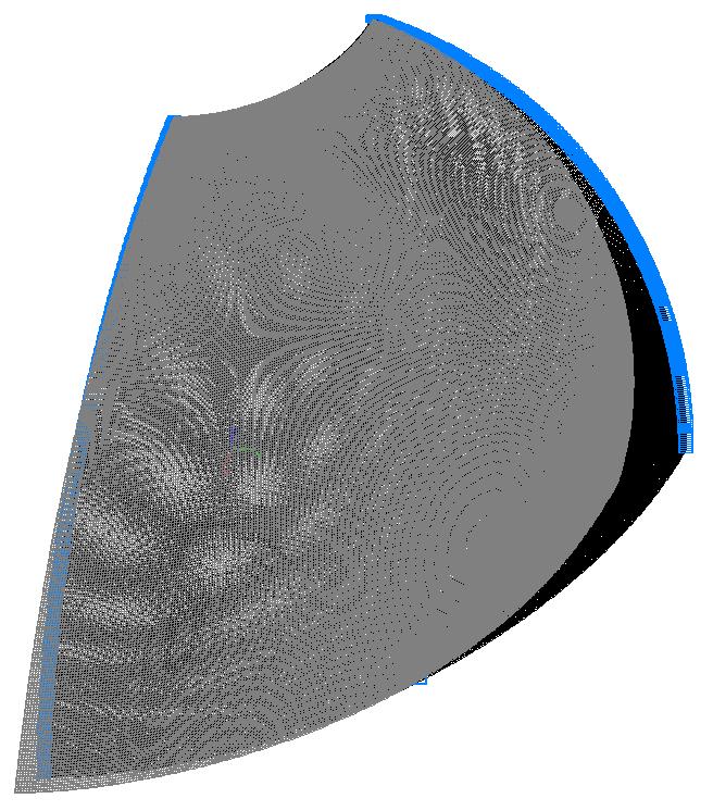
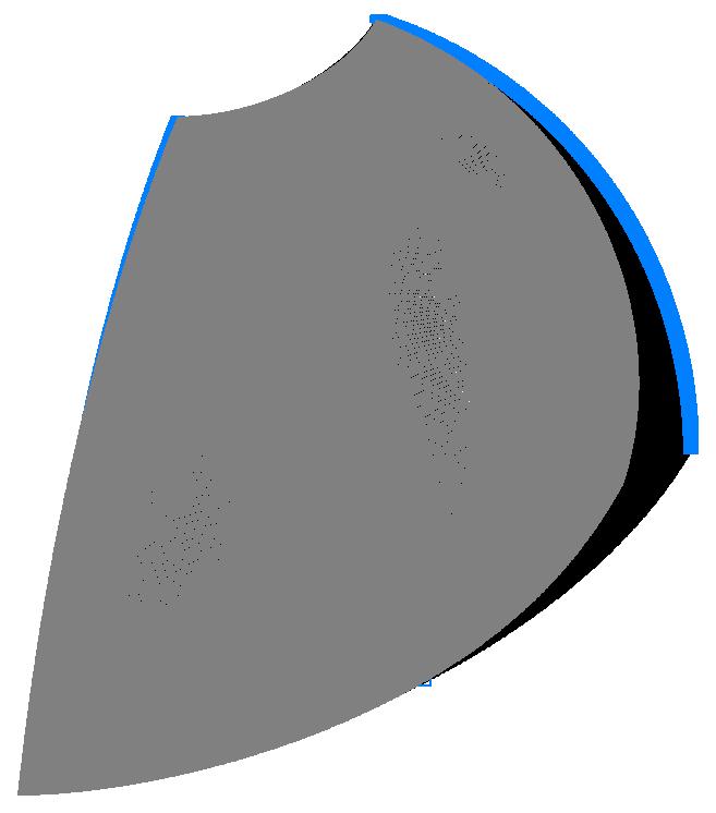
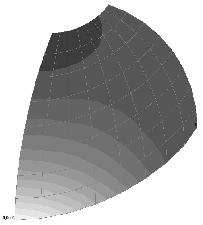
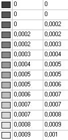
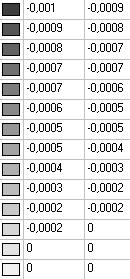
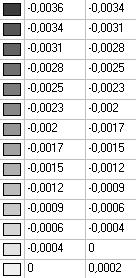
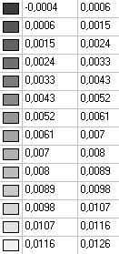
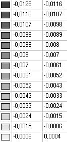
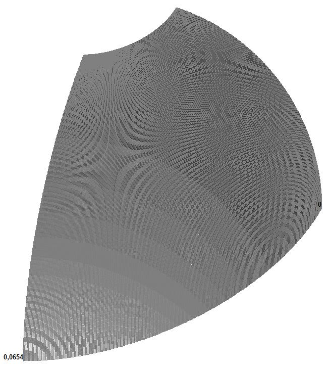
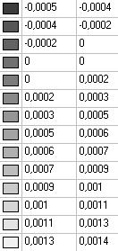
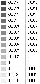
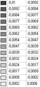
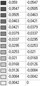
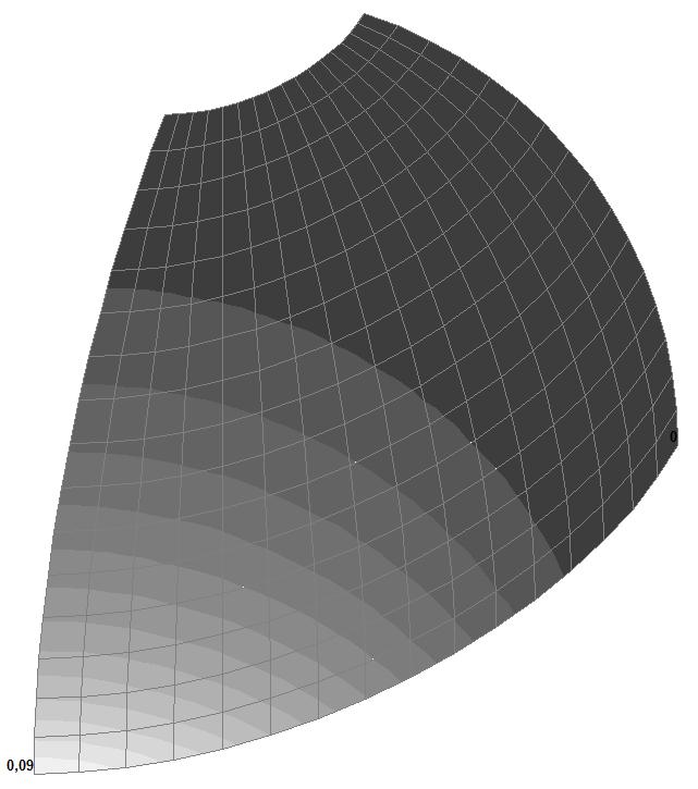
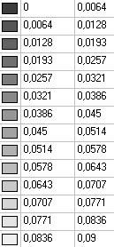
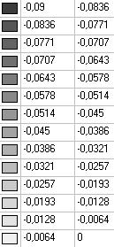
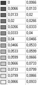
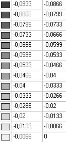
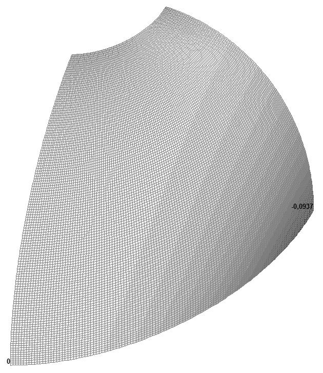
Model 1. Values of the displacements in the direction of the pairs of tensile forces and the pairs of compressive forces along the X and Y axes of the global coordinate system respectively wFX and wFY (m, m)
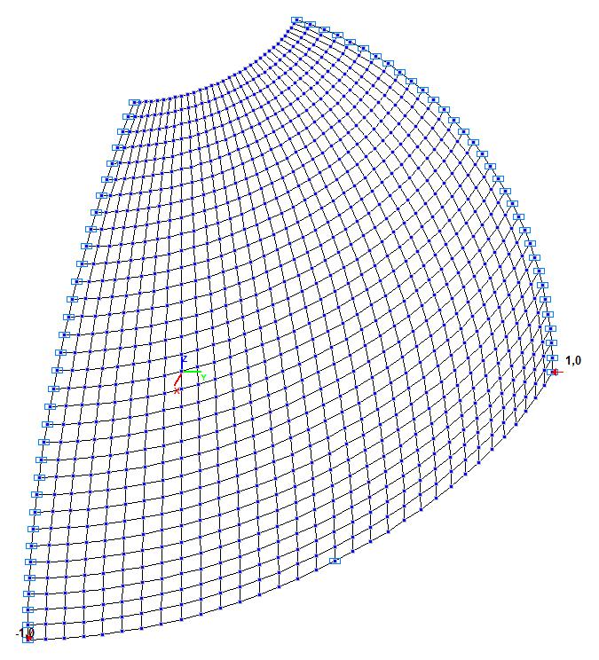
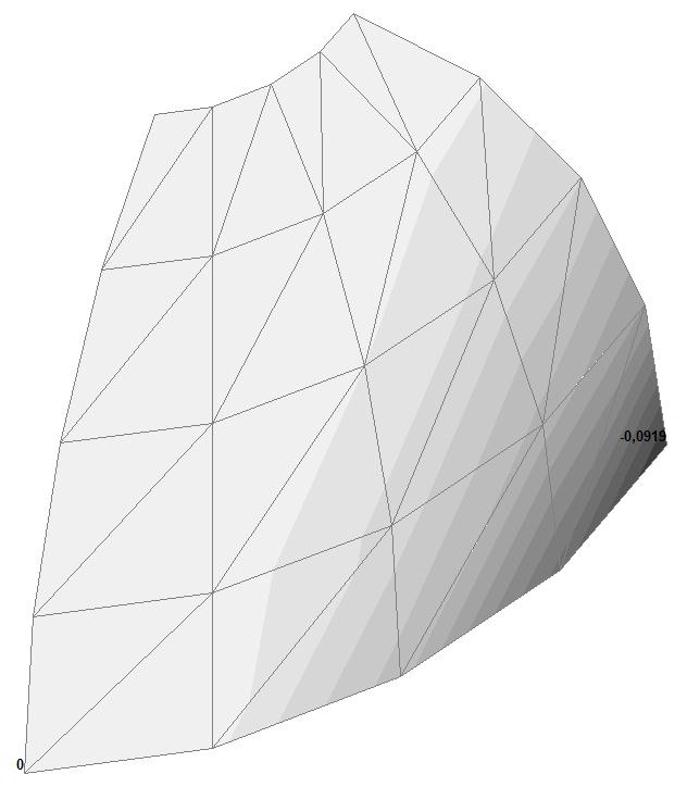
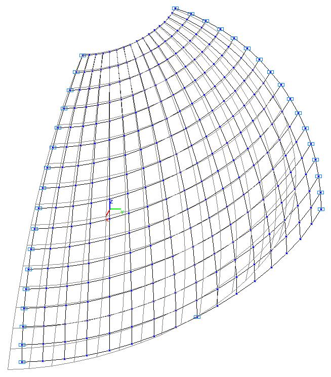
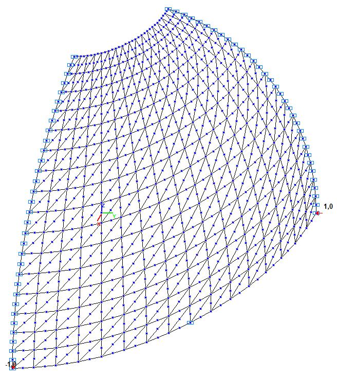
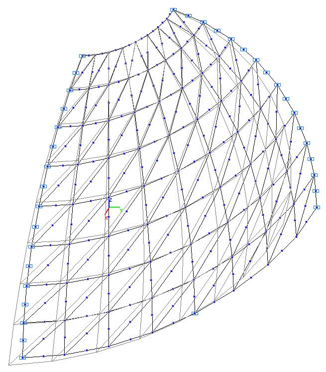
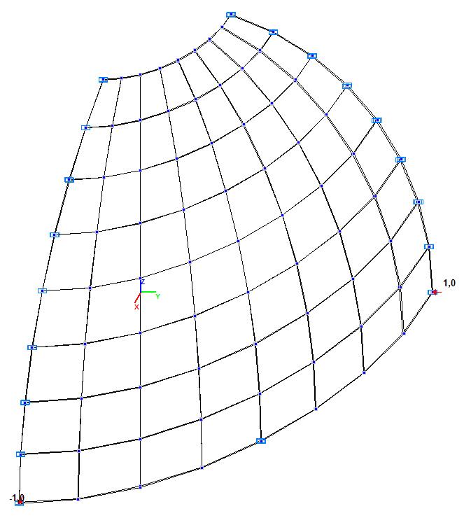
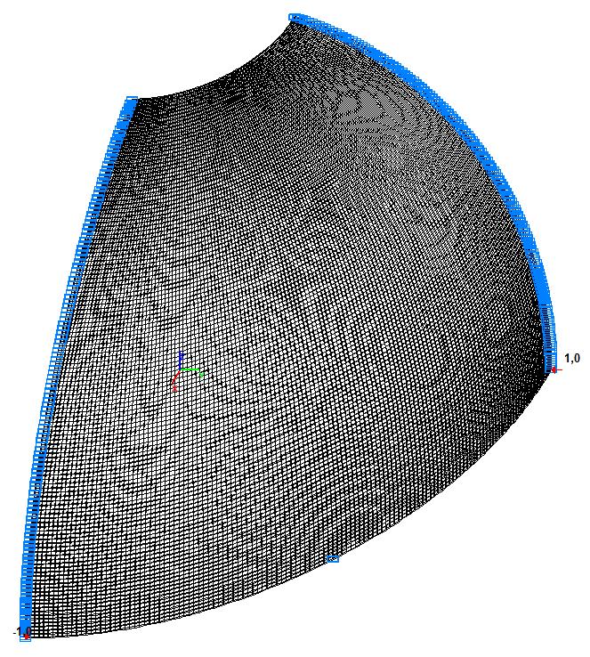
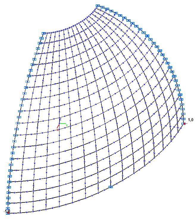
Model 2. Design model
Model 2. Deformed model
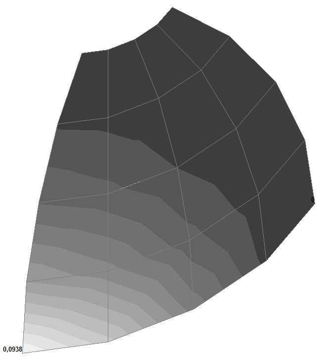
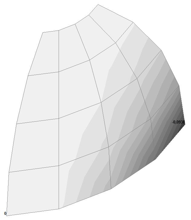


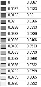

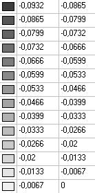
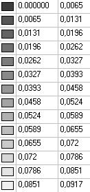
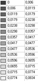
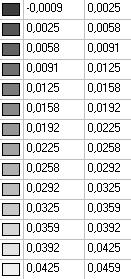
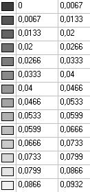
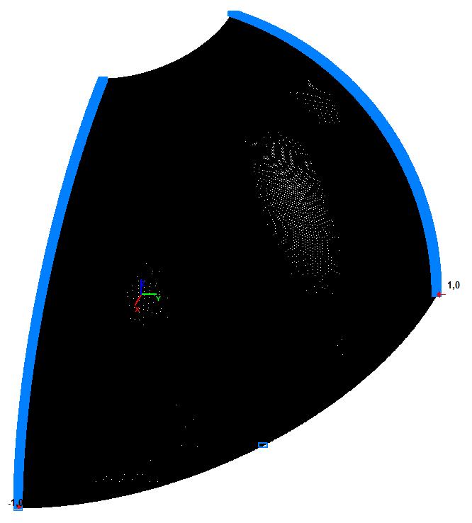
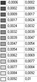
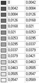
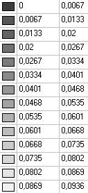
Model 2. Values of the displacements in the direction of the pairs of tensile forces and the pairs of compressive forces along the X and Y axes of the global coordinate system respectively wFX and wFY (m, m)
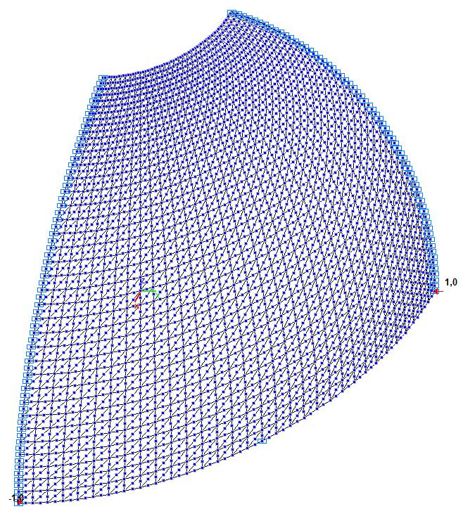
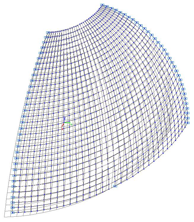
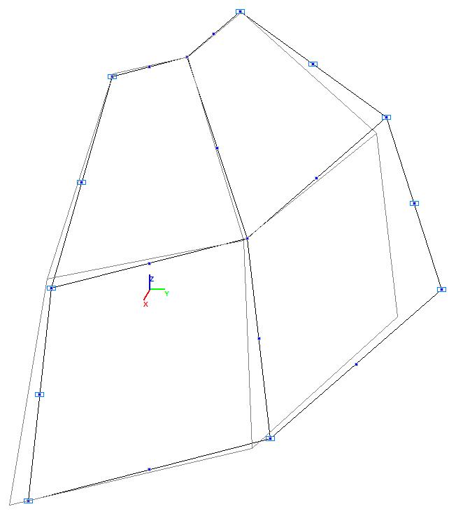
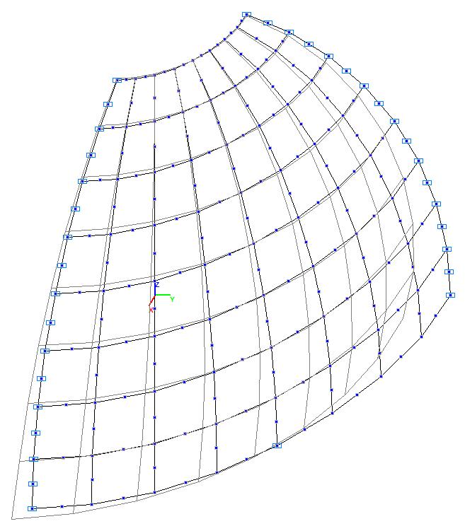
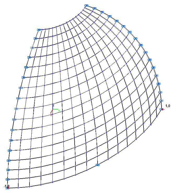
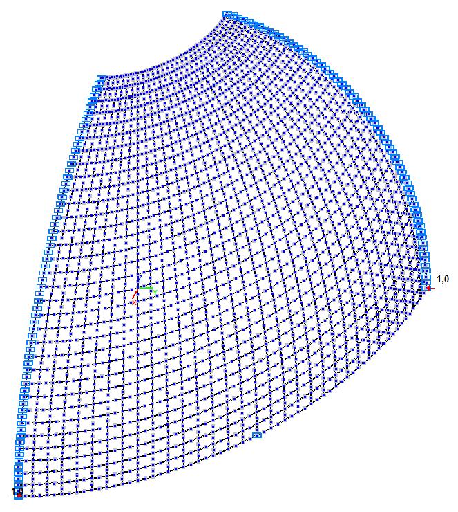
Model 3. Design model
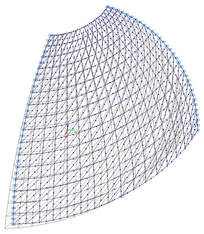
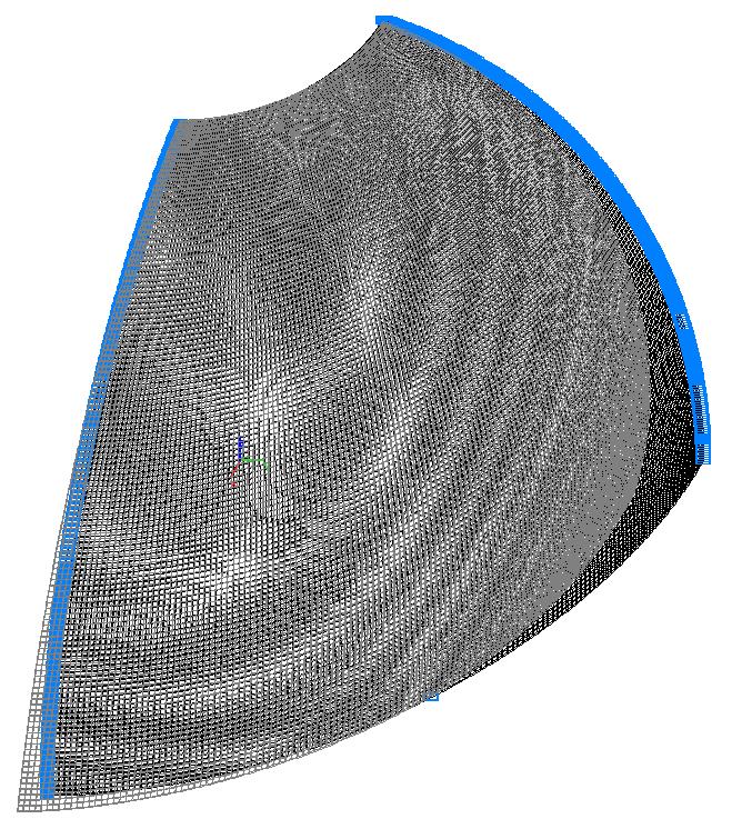
Model 3. Deformed model


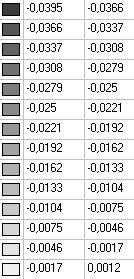

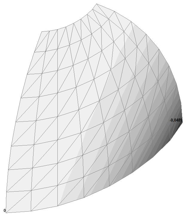


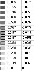


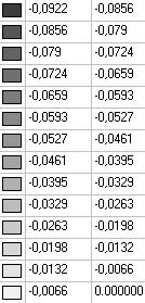
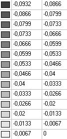
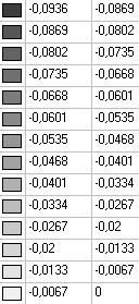
Model 3. Values of the displacements in the direction of the pairs of tensile forces and the pairs of compressive forces along the X and Y axes of the global coordinate system respectively wFX and wFY (m, m)
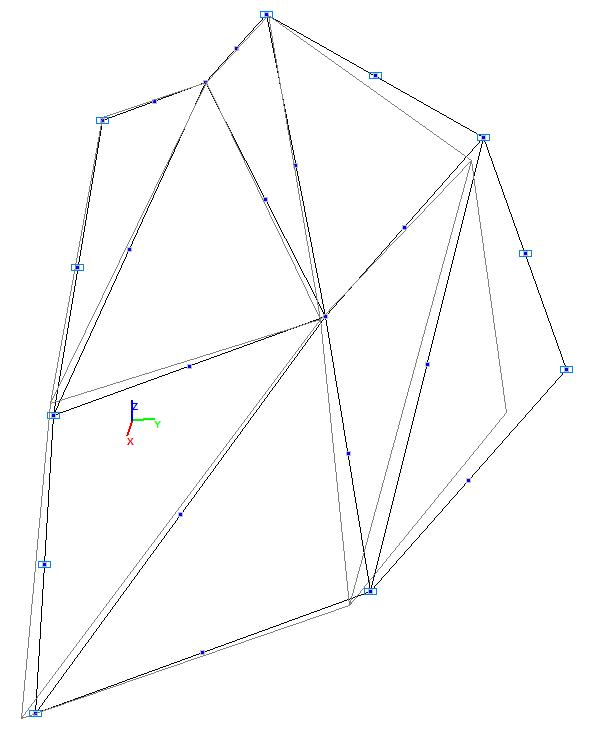
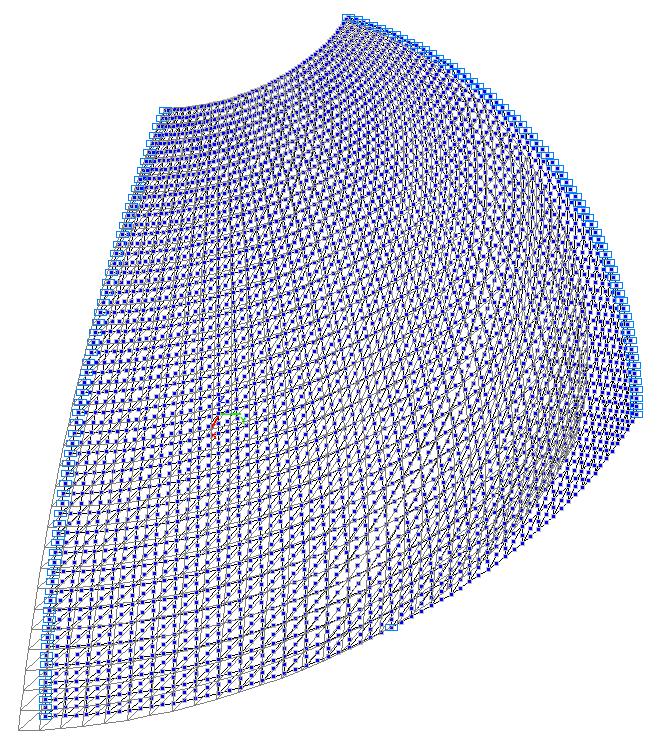
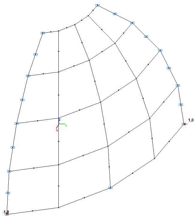
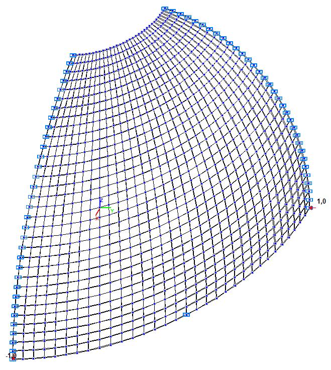
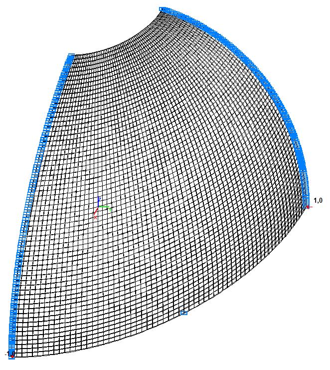
Model 4. Design model
Model 4. Deformed model
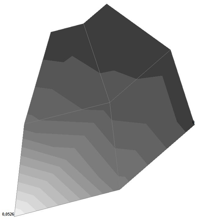


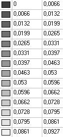
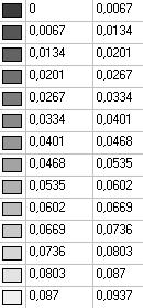
Model 4. Values of the displacements in the direction of the pairs of tensile forces and the pairs of compressive forces along the X and Y axes of the global coordinate system respectively wFX and wFY (m, m)
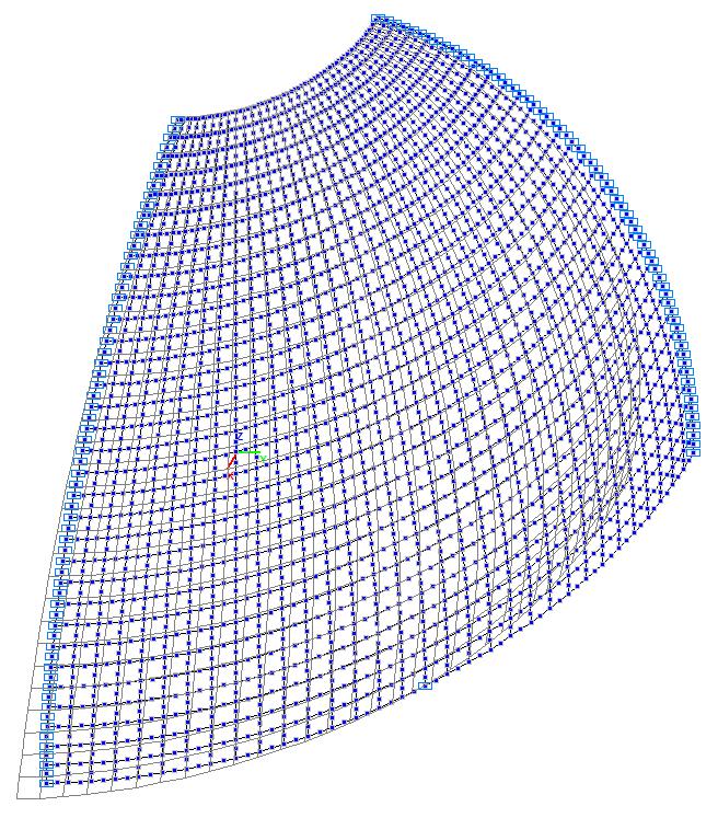
Model 5. Design model

Model 5. Deformed model


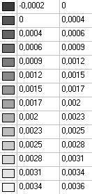


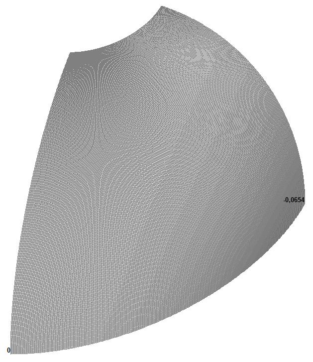
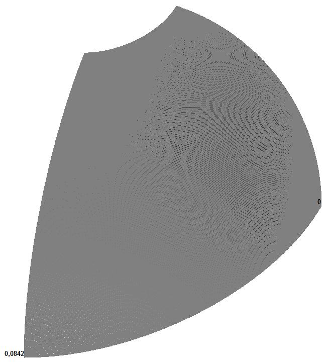
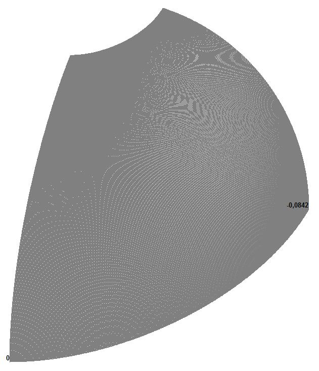
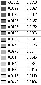
Model 5. Values of the displacements in the direction of the pairs of tensile forces and the pairs of compressive forces along the X and Y axes of the global coordinate system respectively wFX and wFY (m, m)
Model 6. Design model

Model 6. Deformed model
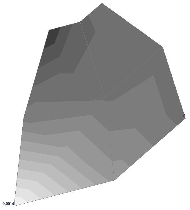


Model 6. Values of the displacements in the direction of the pairs of tensile forces and the pairs of compressive forces along the X and Y axes of the global coordinate system respectively wFX and wFY (m, m)
Comparison of solutions:
Displacements in the direction of the pairs of radial tensile forces and the pairs of radial compressive forces FX and FY along the X and Y axes of the global coordinate system respectively wFX and wFY (m, m)
|
Model |
Finite element mesh |
Theory |
SCAD |
Deviation, % |
|---|---|---|---|---|
|
1 (Member type 42) |
2x2 |
+0.0940 –0.0940 |
+0.0828 –0.0862 |
11.91 8.30 |
|
4x4 |
+0.0902 –0.0919 |
4.04 2.23 |
||
|
8x8 |
+0.0917 –0.0922 |
2.45 1.91 |
||
|
16x16 |
+0.0920 –0.0922 |
2.13 1.91 |
||
|
32x32 |
+0.0927 –0.0928 |
1.38 1.28 |
||
|
2 (Member type 44) |
2x2 |
+0.0940 –0.0940 |
+0.0924 –0.0924 |
1.70 1.70 |
|
4x4 |
+0.0938 –0.0938 |
0.21 0.21 |
||
|
8x8 |
+0.0930 –0.0930 |
1.06 1.06 |
||
|
16x16 |
+0.0928 –0.0928 |
1.28 1.28 |
||
|
32x32 |
+0.0932 –0.0932 |
0.85 0.85 |
||
|
3 (Member type 45) |
2x2 |
+0.0940 –0.0940 |
+0.0506 –0.0510 |
46.17 45.74 |
|
4x4 |
+0.0389 –0.0395 |
58.62 57.98 |
||
|
8x8 |
+0.0484 –0.0489 |
48.51 47.98 |
||
|
16x16 |
+0.0834 –0.0835 |
11.28 11.17 |
||
|
32x32 |
+0.0927 –0.0927 |
1.38 1.38 |
||
|
4 (Member type 50) |
2x2 |
+0.0940 –0.0940 |
+0.0526 –0.0526 |
44.04 44.04 |
|
4x4 |
+0.0459 –0.0459 |
51.17 51.17 |
||
|
8x8 |
+0.0651 –0.0651 |
30.74 30.74 |
||
|
16x16 |
+0.0899 –0.0899 |
4.36 4.36 |
||
|
32x32 |
+0.0932 –0.0932 |
0.85 0.85 |
||
|
5 (Member type 36) |
2x2 |
+0.0940 –0.0940 |
+0.0000 –0.0000 |
100.00 100.00 |
|
4x4 |
+0.0001 –0.0001 |
99.89 99.89 |
||
|
8x8 |
+0.0003 –0.0003 |
99.68 99.68 |
||
|
16x16 |
+0.0010 –0.0010 |
98.94 98.94 |
||
|
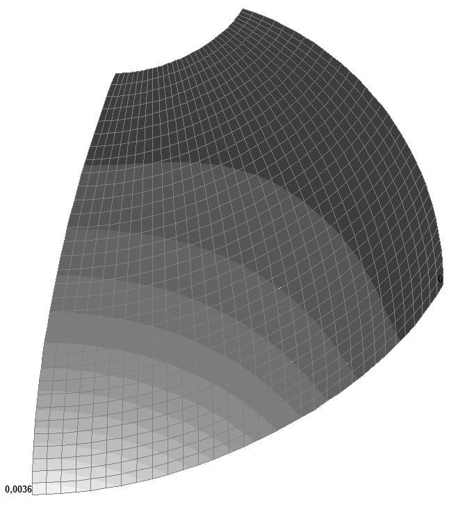
32x32 |
+0.0036 –0.0036 |
96.17 96.17 |
||
|
64x64 |
+0.0126 –0.0126 |
86.60 86.60 |
||
|
128x128 |
+0.0350 –0.0350 |
62.77 62.77 |
||
|
256x256 |
+0.0654 –0.0654 |
30.43 30.43 |
||
|
512x512 |
+0.0842 –0.0842 |
10.43 10.43 |
||
|
6 (Member type 37) |
2x2 |
+0.0940 –0.0940 |
+0.0014 –0.0014 |
98.51 98.51 |
|
4x4 |
+0.0100 –0.0100 |
89.36 89.36 |
||
|
8x8 |
+0.0589 –0.0590 |
37.34 37.23 |
||
|
16x16 |
+0.0900 –0.0900 |
4.26 4.26 |
||
|
32x32 |
+0.0933 –0.0933 |
0.74 0.74 |
||
|
64x64 |
+0.0936 –0.0936 |
0.43 0.43 |
||
|
128x128 |
+0.0937 –0.0937 |
0.32 0.32 |