Stability of a Cantilever Column with a Step Change in Cross-Section Subjected to Longitudinal Compressive Forces Applied to the Intermediate and End Sections

Objective: Determination of the critical values of longitudinal compressive forces applied to the intermediate and end sections of the cantilever column with a step change in cross-section corresponding to the moment of its buckling. Determination of the unsupported lengths of the column steps.
Initial data files:
| File name | Description |
|---|---|
|
Bar model |
|
|
Shell element model |
- Problem formulation: The cantilever column with a step change in cross-section is subjected to longitudinal forces Pi, applied to the intermediate and end sections. Determine the critical values of the longitudinal compressive forces Pcri, corresponding to the moment of the buckling of the cantilever column. Determine the unsupported lengths of the column steps L0i.
References: S. P. Timoshenko, Stability of Bars, Plates and Shells, Moscow, Nauka, 1971, p. 166.
S.D. Ponomarev, V.L. Biederman, K.K. Likharev, V.M. Makushin, N.N. Malinin, V.I. Feodos’yev, Fundamentals of Modern Methods for Strength Analysis in Mechanical Engineering. Dynamic Analysis. Stability. Creep. Moscow, Mashgiz, 1952, p. 543, 555.
Initial data:
| L1 = 10.0 m | - length of the first (upper) step of the column; |
| L2 = 10.0 m | - length of the second (middle) step of the column; |
| L3 = 10.0 m | - length of the third (lower) step of the column; |
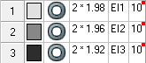
| D1 = 2.0 m | - outer diameter of the circular hollow section of the first step of the column; |
| D2 = 2.0 m | - outer diameter of the circular hollow section of the second step of the column; |
| D3 = 2.0 m | - outer diameter of the circular hollow section of the third step of the column; |
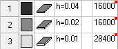
| t1 = 0.01 m | - thickness of the circular hollow section of the first step of the column; |
| t2 = 0.02 m | - thickness of the circular hollow section of the second step of the column; |
| t3 = 0.04 m | - thickness of the circular hollow section of the third step of the column; |
| E = 2.06·108 kN/m2 | - elastic modulus of the column material; |
| ν = 0.3 | - Poisson’s ratio; |
| P1 = 1.0·104 kN/m2 | - initial value of the compressive longitudinal force applied to the upper edge of the first step of the column; |
| P2 = 1.0·104 kN/m2 | - initial value of the compressive longitudinal force applied to the upper edge of the second step of the column; |
| P3 = 2.0·104 kN/m2 | - initial value of the compressive longitudinal force applied to the upper edge of the third step of the column; |
Finite element model: Two design models are considered:
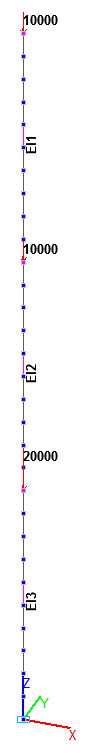
Bar model, design model – plane frame, 30 bar elements of the plane frame of type 2. The spacing of the finite element mesh along the longitudinal axis of the column (along the X1 axes of the local coordinate systems) is 1.0 m. Boundary conditions are provided by imposing constraints on the clamped node of the column in the directions of the degrees of freedom X, Y, Z, UX, UY, UZ. Concentrated forces with the initial values P1, P2, P3 are specified in the nodes of the upper edges of the column steps. Number of nodes – 31.
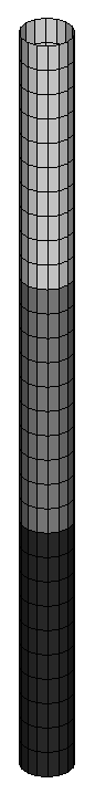
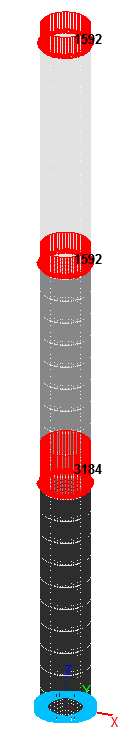
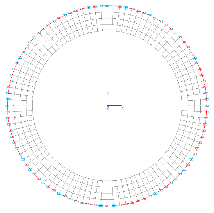
Shell element model, design model – general type system, 60400 four-node shallow shell elements allowing for shear of type 150. The spacing of the finite element mesh of the column in the circumferential direction (along the X1 axes of the local coordinate systems) is 3.6°, and along the longitudinal axis (along the Y1 axes of the local coordinate systems) is 0.0625 m. Horizontal ring stiffeners 0.25 m wide are arranged with a vertical spacing of 1.00 m inside the column in order to prevent the local buckling of its shell. The spacing of the finite element mesh of the stiffeners in the radial direction (along the Y1 axes of the local coordinate systems) is 0.0625 m. Boundary conditions are provided by imposing constraints on the nodes of the clamped edge in the directions of the degrees of freedom X, Y, Z, UX, UY, UZ. Loads uniformly distributed along the line with the initial values P1/(π·D1), P2/(π·D2), P3/(π·D3) are specified in the nodes of the upper edges of the column steps. Number of nodes – 60500.
Results in SCAD
Bar model
Shell element model
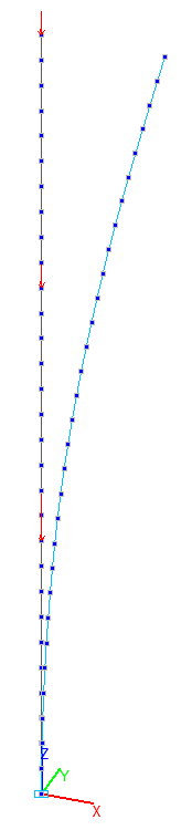
1-st buckling mode for the bar model
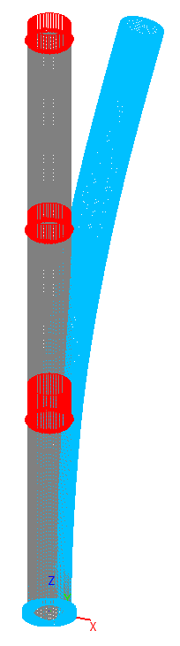
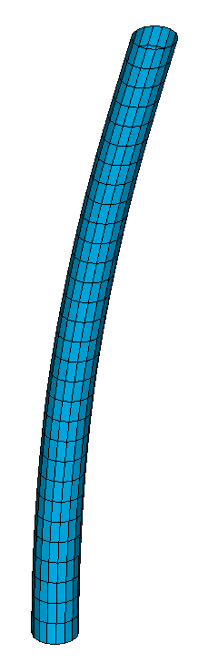
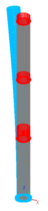
1-st buckling mode for the shell element model
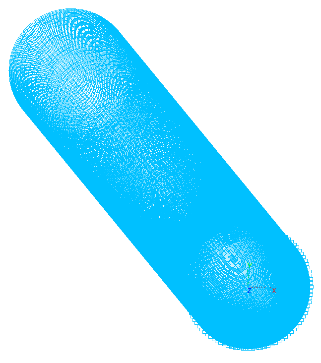
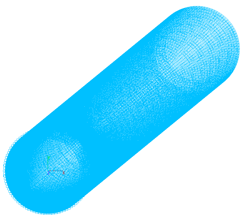
2-nd buckling mode for the shell element model
Comparison of solutions:
|
Parameter |
Theory |
SCAD |
|||
|---|---|---|---|---|---|
|
Bar model |
Deviation, % |
Shell element model |
Deviation, % |
||
|
Critical value of the concentrated longitudinal force applied to the upper edge of the first step Pcr1, kN |
32978 |
3.297920∙ ·10000 = = 32979 |
0.00 |
3.394470∙ ·10000 = = 33945 |
2.93 |
|
Critical value of the concentrated longitudinal force applied to the upper edge of the second step Pcr2, kN |
32978 |
3.297920∙ ·10000 = = 32979 |
0.00 |
3.394470∙ ·10000 = = 33945 |
2.93 |
|
Critical value of the concentrated longitudinal force applied to the upper edge of the third step Pcr3, kN |
65957 |
3.297920∙ ·20000 = = 65958 |
0.00 |
3.394470∙ ·20000 = = 67890 |
2.93 |
|
Unsupported length of the first column step L01, m |
43.680 |
43.681 |
0.00 |
— |
— |
|
Unsupported length of the second column step L02, m |
43.353 |
43.353 |
0.00 |
— |
— |
|
Unsupported length of the third column step L03, m |
42.704 |
42.705 |
0.00 |
— |
— |
Notes: In the analytical solution the critical values of the longitudinal compressive forces Pcri, corresponding to the moment of the buckling of the cantilever column and unsupported lengths of the column steps L0i can be determined according to the following formulas:
\[ P_{cr1} =k\cdot P_{1} ; \quad P_{cr2} =k\cdot P_{2} ; \quad P_{cr3} =k\cdot P_{3} ; \] \[ L_{01} =\pi \cdot \sqrt {\frac{E\cdot I_{1} }{k\cdot P_{1} }} ; \quad L_{02} =\pi \cdot \sqrt {\frac{E\cdot I_{2} }{k\cdot \left( {P_{1} +P_{2} } \right)}} ; \quad L_{03} =\pi \cdot \sqrt {\frac{E\cdot I_{3} }{k\cdot \left( {P_{1} +P_{2} +P_{3} } \right)}} , \quad where\]
k – stability factor of safety of the system is determined on the basis of the condition of equality to zero of the determinant of the system of governing equations:
\[ \left| {{\begin{array}{*{20}c} {\sin \left[ {\sqrt {\frac{k\cdot P_{1} }{E\cdot I_{1} }} \cdot \left( {L_{1} +L_{2} +L_{3} } \right)} \right]} & {\cos \left[ {\sqrt {\frac{k\cdot P_{1} }{E\cdot I_{1} }} \cdot \left( {L_{1} +L_{2} +L_{3} } \right)} \right]} & 0 \\ 0 & 0 & 0 \\ {\frac{P_{1} }{P_{1} +P_{2} }\cdot \sin \left[ {\sqrt {\frac{k\cdot P_{1} }{E\cdot I_{1} }} \cdot \left( {L_{2} +L_{3} } \right)} \right]} & {\frac{P_{1} }{P_{1} +P_{2} }\cdot \cos \left[ {\sqrt {\frac{k\cdot P_{1} }{E\cdot I_{1} }} \cdot \left( {L_{2} +L_{3} } \right)} \right]} & {-\sin \left[ {\sqrt {\frac{k\cdot \left( {P_{1} +P_{2} } \right)}{E\cdot I_{2} }} \cdot \left( {L_{2} +L_{3} } \right)} \right]} \\ {\sqrt {\frac{k\cdot P_{1} }{E\cdot I_{1} }} \cdot \cos \left[ {\sqrt {\frac{k\cdot P_{1} }{E\cdot I_{1} }} \cdot \left( {L_{2} +L_{3} } \right)} \right]} & {-\sqrt {\frac{k\cdot P_{1} }{E\cdot I_{1} }} \cdot \sin \left[ {\sqrt {\frac{k\cdot P_{1} }{E\cdot I_{1} }} \cdot \left( {L_{2} +L_{3} } \right)} \right]} & {-\sqrt {\frac{k\cdot \left( {P_{1} +P_{2} } \right)}{E\cdot I_{2} }} \cdot \cos \left[ {\sqrt {\frac{k\cdot \left( {P_{1} +P_{2} } \right)}{E\cdot I_{2} }} \cdot \left( {L_{2} +L_{3} } \right)} \right]} \\ 0 & 0 & {\frac{P_{1} +P_{2} }{P_{1} +P_{2} +P_{3} }\cdot \sin \left[ {\sqrt {\frac{k\cdot \left( {P_{1} +P_{2} } \right)}{E\cdot I_{2} }} \cdot L_{3} } \right]} \\ 0 & 0 & {\sqrt {\frac{k\cdot \left( {P_{1} +P_{2} } \right)}{E\cdot I_{2} }} \cdot \cos \left[ {\sqrt {\frac{k\cdot \left( {P_{1} +P_{2} } \right)}{E\cdot I_{2} }} \cdot L_{3} } \right]} \\ \end{array} }} \right. \] \[ \left. {{\begin{array}{*{20}c} 0 & 0 & 0 \\ 0 & {\sqrt {\frac{k\cdot \left( {P_{1} +P_{2} +P_{3} } \right)}{E\cdot I_{3} }} } & 0 \\ {-\cos \left[ {\sqrt {\frac{k\cdot \left( {P_{1} +P_{2} } \right)}{E\cdot I_{2} }} \cdot \left( {L_{2} +L_{3} } \right)} \right]} & 0 & 0 \\ {\sqrt {\frac{k\cdot \left( {P_{1} +P_{2} } \right)}{E\cdot I_{2} }} \cdot \sin \left[ {\sqrt {\frac{k\cdot \left( {P_{1} +P_{2} } \right)}{E\cdot I_{2} }} \cdot \left( {L_{2} +L_{3} } \right)} \right]} & 0 & 0 \\ {\frac{P_{1} +P_{2} }{P_{1} +P_{2} +P_{3} }\cdot \cos \left[ {\sqrt {\frac{k\cdot \left( {P_{1} +P_{2} } \right)}{E\cdot I_{2} }} \cdot L_{3} } \right]} & {-\sin \left[ {\sqrt {\frac{k\cdot \left( {P_{1} +P_{2} +P_{3} } \right)}{E\cdot I_{3} }} \cdot L_{3} } \right]} & {-\cos \left[ {\sqrt {\frac{k\cdot \left( {P_{1} +P_{2} +P_{3} } \right)}{E\cdot I_{3} }} \cdot L_{3} } \right]} \\ {-\sqrt {\frac{k\cdot \left( {P_{1} +P_{2} } \right)}{E\cdot I_{2} }} \cdot \sin \left[ {\sqrt {\frac{k\cdot \left( {P_{1} +P_{2} } \right)}{E\cdot I_{2} }} \cdot L_{3} } \right]} & {-\sqrt {\frac{k\cdot \left( {P_{1} +P_{2} +P_{3} } \right)}{E\cdot I_{3} }} \cdot \cos \left[ {\sqrt {\frac{k\cdot \left( {P_{1} +P_{2} +P_{3} } \right)}{E\cdot I_{3} }} \cdot L_{3} } \right]} & {\sqrt {\frac{k\cdot \left( {P_{1} +P_{2} +P_{3} } \right)}{E\cdot I_{3} }} \cdot \sin \left[ {\sqrt {\frac{k\cdot \left( {P_{1} +P_{2} +P_{3} } \right)}{E\cdot I_{3} }} \cdot L_{3} } \right]} \\ \end{array} }} \right|=0 \]