Stability of a Cantilever Beam of a Square Cross-Section Subjected to a Concentrated Longitudinal Compressive Force Centrally Applied at the Free End (Central Compression)

Objective: Determination of the first two critical values of a concentrated longitudinal compressive force centrally applied at the free end of a cantilever beam of a square cross-section corresponding to the moments of its buckling.
Initial data files:
|
File name |
Description |
|---|---|
|
Bar model |
|
|
Shell element model |
|
|
Solid element model |
Problem formulation: The cantilever beam of a square cross-section is subjected to the action of the concentrated longitudinal compressive force P, centrally applied at its free end. Determine the first two critical values of the concentrated longitudinal compressive force Pcr1 and Pcr2, corresponding to the moments of buckling of the cantilever beam.
References: A.S. Volmir. Stability of Deformable Systems, Moscow, Nauka, 1967, p.23, 193;
Initial data:
| L = 10.0 m | - length of the cantilever beam; |
| h = b = 1.0 m | - side of the square cross-section of the cantilever beam; |
| E = 3.0·107 kN/m2 | - elastic modulus of the cantilever beam material; |
| ν = 0.2 | - Poisson’s ratio; |
| P = 105 kN | - initial value of the concentrated longitudinal compressive force centrally applied at the free end of the beam. |
Finite element model: Design model – general type system. Three design models are considered:
Bar model (B), 10 elements of type 5, the spacing of the finite element mesh along the longitudinal axis is 1.0 m. Boundary conditions are provided by imposing constraints on the node of the clamped end of the beam in the directions of the degrees of freedom X, Y, Z, UX, UY, UZ. The action with the initial value of the concentrated longitudinal compressive force P is specified in the node of the free end of the beam. Number of nodes in the design model – 11;
Reissner-Mindlin shell element model (P), 2560 eight-node elements of type 150, the spacing of the finite element mesh along the longitudinal axis and along the height of the beam is 0.0625 m. Boundary conditions are provided by imposing constraints on the nodes of the clamped end of the beam in the directions of the degrees of freedom X, Y, Z, UX, UY, UZ. The action with the initial value of the concentrated longitudinal compressive force P is specified in the node of the longitudinal axis of the beam on the free end. Number of nodes in the design model – 8033.
Solid element model (S), 5120 twenty-node elements of type 37, the spacing of the finite element mesh along the longitudinal axis, width and height of the beam is 0.125 m. Boundary conditions are provided by imposing constraints on the nodes of the clamped end of the beam in the directions of the degrees of freedom X, Y, Z, UX, UY, UZ. The action with the initial value of the concentrated longitudinal compressive force P is specified as a load uniformly distributed over the external faces of the elements of the beam end p = P/(h·b). Number of nodes in the design model – 24705.
Results in SCAD
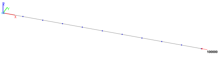
Design model. Bar model
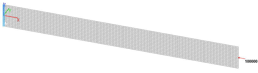
Design model. Reissner-Mindlin shell element model
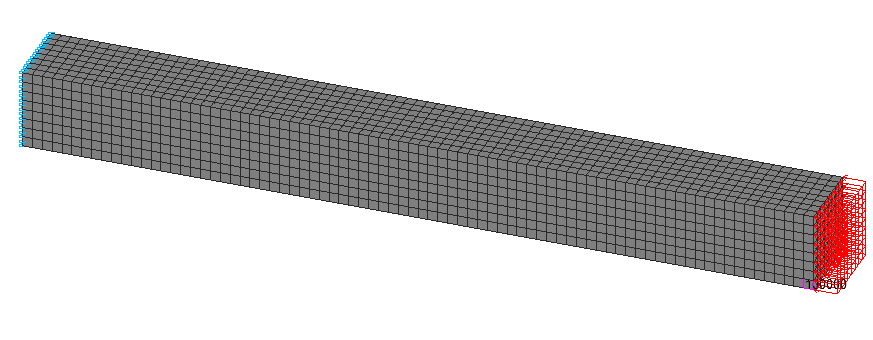
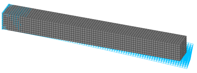
Design model. Solid element model
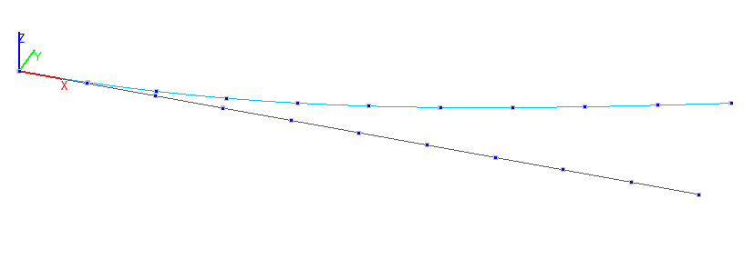
1-st buckling mode. Bar model
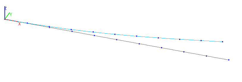
2-nd buckling mode. Bar model
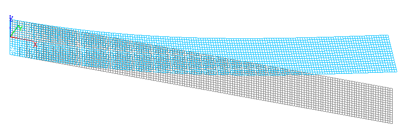
1-st buckling mode. Reissner-Mindlin shell element model
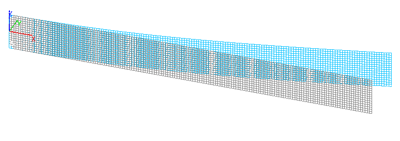
2-nd buckling mode. Reissner-Mindlin shell element model
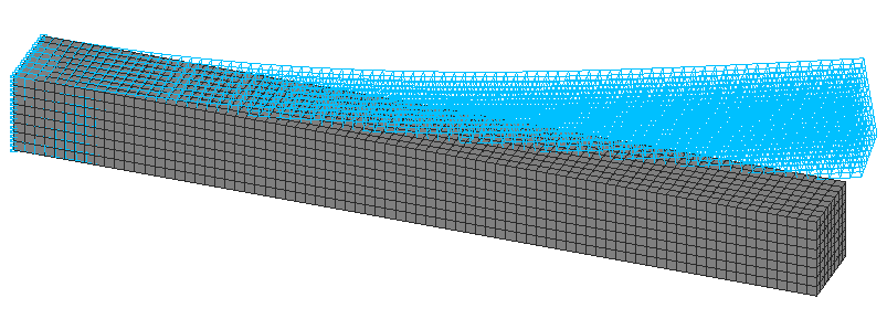
1- st buckling mode. Solid element model
2- nd buckling mode. Solid element model
Comparison of solutions:
Critical values of the concentrated longitudinal compressive force Pcr1 and Pcr2 (kN), centrally applied at the free end of the beam
|
Design model |
Buckling mode |
Theory |
SCAD |
Deviation, % |
|---|---|---|---|---|
|
Bar |
1-st |
61685 |
0,616821∙100000=61682 |
0,01 |
|
2-nd |
61685 |
0,616821∙100000= 61682 |
0,01 |
|
|
Reissner-Mindlin shell element |
1-st |
61685 |
0,613922∙100000=61392 |
0,48 |
|
2-nd |
61685 |
0,617533∙100000=61753 |
0,11 |
|
|
Solid element |
1-st |
61685 |
0,613281∙100000=61328 |
0,58 |
|
2-nd |
61685 |
0,613281∙100000=61328 |
0,58 |
Notes: In the analytical solution the critical values of the concentrated longitudinal compressive force Pcr1 and Pcr2, corresponding to the moments of buckling of the cantilever beam can be determined according to the following formulas:
\[ P_{cr1} =\frac{\pi^{2}\cdot E\cdot I_{y} }{4\cdot L^{2}} \quad P_{cr2} =\frac{\pi^{2}\cdot E\cdot I_{z} }{4\cdot L^{2}} \] \[ I_{y} =\frac{b\cdot h^{3}}{12} \quad I_{z} =\frac{h\cdot b^{3}}{12} \]