Stability of a Cantilever Beam of a Square Cross-Section Subjected to a Concentrated Transverse Bending Force Applied to the Upper Edge of the Free End
Objective: Determination of the critical value of the concentrated transverse bending force applied to the upper edge of the free end of a cantilever beam of a square cross-section corresponding to the moment of its buckling.
Initial data files:
|
File name |
Description |
|---|---|
|
Bar model |
|
|
Shell element model |
|
|
Solid element model |
Problem formulation: The cantilever beam of a square cross-section is subjected to the action of the concentrated transverse bending force P, applied to the upper edge of its free end. Determine the critical value of the concentrated transverse bending force Pcr, corresponding to the moment of buckling of the cantilever beam.
References: .S. Volmir, Stability of Deformable Systems, Moscow, Nauka, 1967, p.216;
Initial data:
| L = 10.0 m | - length of the cantilever beam; |
| h = b = 1.0 m | - side of the square cross-section of the cantilever beam; |
| h/2 = 0.5 m | - height of the application point of the concentrated transverse bending force with respect to the longitudinal axis of the beam (X axis of the global coordinate system); |
| E = 3.0·107 kN/m2 | - elastic modulus of the cantilever beam material; |
| ν = 0.2 | - Poisson’s ratio; |
| P = 105 kN | - initial value of the concentrated transverse bending force applied to the upper edge of the free end of the beam. |
Finite element model: Design model – general type system. Three design models are considered:
Bar model (B), 10 elements of type 5, the spacing of the finite element mesh along the longitudinal axis is 1.0 m. Boundary conditions are provided by imposing constraints on the node of the clamped end of the beam in the directions of the degrees of freedom X, Y, Z, UX, UY, UZ. 1 vertical upward two-node element of type 100 (3D rigid body) with the length h/2 is adjacent to the node of the free end of the beam. The action with the initial value of the concentrated transverse bending force P is specified in the free node of the element of the rigid body (elevated application point). Number of nodes in the design model – 12.
Reissner-Mindlin shell element model (P), 2560 eight-node elements of type 150, the spacing of the finite element mesh along the longitudinal axis and along the height of the beam is 0.0625 m. Boundary conditions are provided by imposing constraints on the nodes of the clamped end of the beam in the directions of the degrees of freedom X, Y, Z, UX, UY, UZ. The action with the initial value of the concentrated transverse bending force P is specified in the node on the free end at the height h/2 from the longitudinal axis of the beam. Number of nodes in the design model – 8033.
Solid element model (S), 5120 twenty-node elements of type 37, the spacing of the finite element mesh along the longitudinal axis, width and height of the beam is 0.125 m. Boundary conditions are provided by imposing constraints on the nodes of the clamped end of the beam in the directions of the degrees of freedom X, Y, Z, UX, UY, UZ. The action with the initial value of the concentrated transverse bending force P is specified as a group of nodal forces on the upper edge of the free end of the beam Pi = P·0.0625/1.0 = 6250 kN (3125 kN for corner nodes). Number of nodes in the design model – 24705.
Results in SCAD
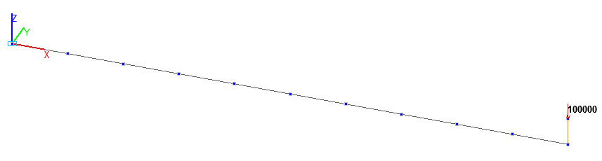
Design model. Bar model
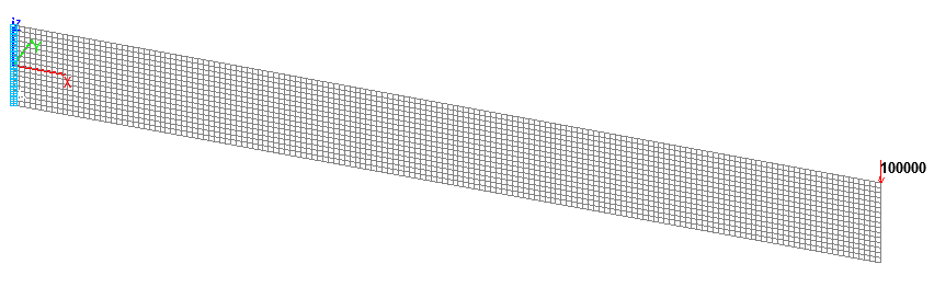
Design model. Reissner-Mindlin shell element model
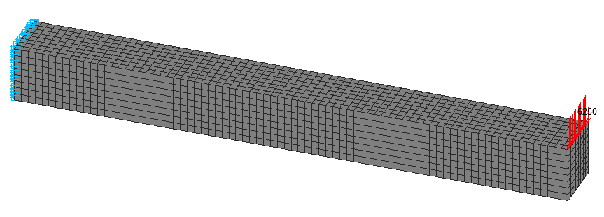
Design model. Solid element model
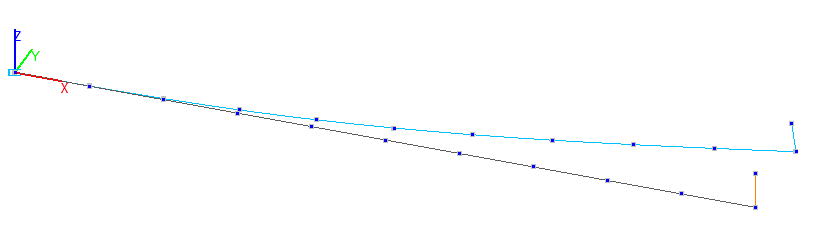
1-st buckling mode. Bar model
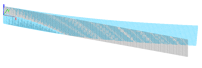
1-st buckling mode. Reissner-Mindlin shell element model
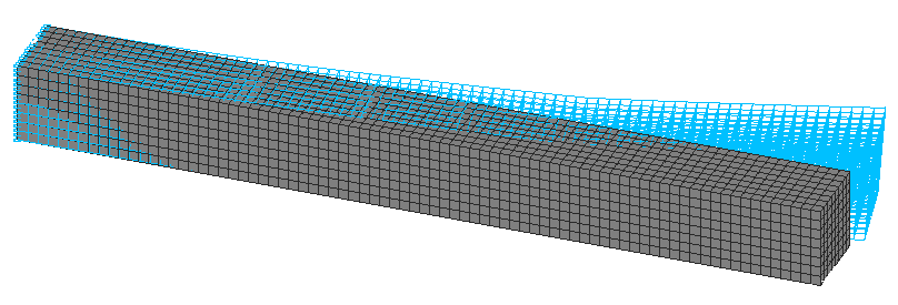
1-st buckling mode. Solid element model
Comparison of solutions:
Critical value of the concentrated transverse bending force Pcr (kN), applied to the upper edge of the free end of the beam
|
Design model |
Theory |
SCAD |
Deviation, % |
|---|---|---|---|
|
Bar |
78305 |
0,778008∙100000=77801 |
0,64 |
|
Reissner-Mindlin shell element |
78305 |
0,768958∙100000=76896 |
1,80 |
|
Solid element |
78305 |
0,816406∙100000=81641 |
4,26 |
Notes: In the analytical solution the critical value of the concentrated transverse bending force Pcr, corresponding to the moment of buckling of the cantilever beam can be determined according to the following formula:
\[ P=\frac{4,01\cdot \sqrt {E\cdot I_{z} \cdot G\cdot I_{x} } }{L^{2}}\cdot k_{h} \quad G=\frac{E}{2\cdot \left( {1+\nu } \right)} \quad k_{h} =f\left( {\frac{h}{2\cdot L}\cdot \sqrt {\frac{E\cdot I_{z} }{G\cdot I_{x} }} } \right) \]
\( I_{z} =\frac{h\cdot b^{3}}{12} \) – minimum bending inertia moment (out of the moment plane);
\( I_{x} =k_{f} \cdot h\cdot b^{3} \) – free torsional inertia moment, where:
\[ k_{f} =\frac{1}{3}\cdot \left\{ {1-\frac{192}{\pi^{5}}\cdot \frac{b}{h}\cdot \sum\limits_{n=1}^\infty {\left[ {\sin^{2}\left( {\frac{n\cdot \pi }{2}} \right)\cdot \frac{1}{n^{5}}\cdot th\left( {\frac{n\cdot \pi \cdot h}{2\cdot b}} \right)} \right]} } \right\} \]