Stability of a Beam of a Square Cross-Section Simply Supported in and out of the Bending Plane Subjected to Concentrated Longitudinal Bending Forces Applied to the Upper Edges of the Ends and Equal in Value (Longitudinal Bending)

Objective: Determination of the first two critical values of concentrated longitudinal bending forces equal in value and applied to the upper edges of the ends of a beam of a square cross-section simply supported in and out of the bending plane corresponding to the moment of its buckling.
Initial data files:
|
File name |
Description |
|---|---|
|
Bar model |
|
|
Shell element model |
Problem formulation: The beam of a square cross-section simply supported in and out of the bending plane is subjected to the action of the concentrated longitudinal bending forces P, equal in value and applied to the upper edges of its ends. Determine first two critical values of the concentrated longitudinal bending forces Pcr1 and Pcr2, corresponding to the moment of buckling of the simply supported beam.
References: S. P. Timoshenko, Stability of Bars, Plates and Shells, Moscow, Nauka, 1971, p.291
Initial data:
| L = 10.0 m | - length of the simply supported beam; |
| h = b = 1.0 m | - side of the square cross-section of the simply supported beam; |
| E = 3.0·107 kN/m2 | - elastic modulus of the simply supported beam material; |
| ν = 0.2 | - Poisson’s ratio; |
| P = 106 kN | - initial value of the concentrated longitudinal bending forces applied to the upper edges of the ends of the beam. |
Finite element model: Design model – general type system. Two design models are considered:
Bar model (B), 10 elements of type 5, the spacing of the finite element mesh along the longitudinal axis is 1.0 m. Boundary conditions are provided by imposing constraints on the nodes of the simply supported ends of the beam in the directions of the degrees of freedom Y, Z. The dimensional stability is provided by imposing constraints on the node in the middle of the beam span in the directions of the degrees of freedom X, UX. 2 vertical upward two-node elements of type 100 (3D rigid body) with the length h/2 are adjacent to the nodes of the ends of the beam. The action with the initial value of the concentrated longitudinal bending forces P is specified in the free nodes of the elements of the rigid bodies (elevated application points). Number of nodes in the design model – 13.
Reissner-Mindlin shell element model (P), 2560 eight-node elements of type 150, the spacing of the finite element mesh along the longitudinal axis and along the height of the beam is 0.0625 m. The shell is supported by vertical high-rigidity bars (h = b = 1.0 m; E = 3.0·109 kN/m2; ν = 0.2), 64 elements of type 5. Boundary conditions are provided by imposing constraints on the nodes of the ends of the beam lying on its longitudinal axis in the directions of the degrees of freedom Y, Z and on all other nodes of the ends of the beam in the direction of the degree of freedom Y. The dimensional stability is provided by imposing a constraint on the node in the middle of the beam span along its longitudinal axis in the direction of the degree of freedom X. The action with the initial value of the concentrated longitudinal bending forces P is specified in the nodes on the ends at the height h/2 from the longitudinal axis of the beam. Number of nodes in the design model – 8033.
Results in SCAD
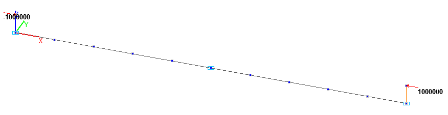
Design model. Bar model
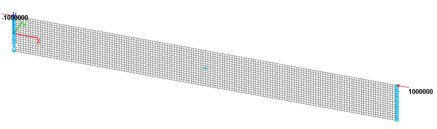
Design model. Reissner-Mindlin shell element model
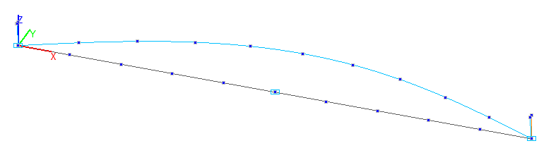
1- st buckling mode. Bar model
2- nd buckling mode. Bar model
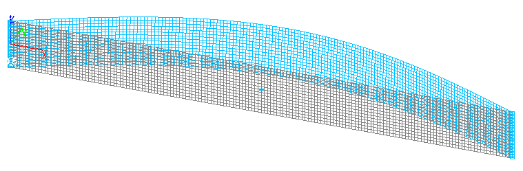
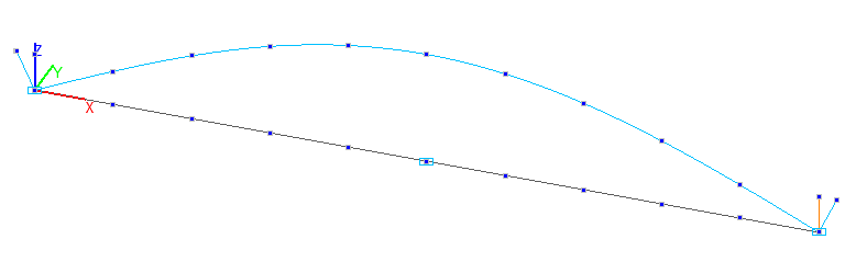
1- st buckling mode. Reissner-Mindlin shell element model
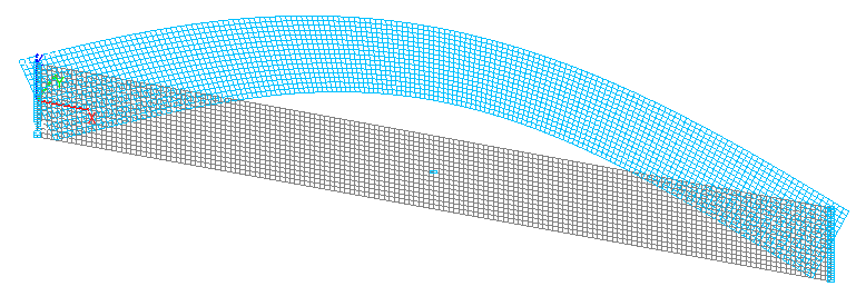
2-nd buckling mode. Reissner-Mindlin shell element model
Comparison of solutions:
Critical values of the concentrated longitudinal bending forces Pcr1 and Pcr2 (kN), applied to the upper edges of the ends of the beam simply supported in and out of the bending plane
|
Design model |
Buckling mode |
Theory |
SCAD |
Deviation, % |
|---|---|---|---|---|
|
Bar |
1-st |
61685 |
0,616821∙100000=61682 |
0,01 |
|
2-nd |
61685 |
0,616821∙100000=61682 |
0,01 |
|
|
Reissner-Mindlin shell element |
1-st |
61685 |
0,613922∙100000=61392 |
0,48 |
|
2-nd |
61685 |
0,617533∙100000=61753 |
0,11 |
Notes: In the analytical solution the critical values of the concentrated longitudinal bending forces Pcr1 and Pcr2, corresponding to the moments of buckling of the simply supported beam can be determined according to the following formulas:
\[ P_{1} =\frac{2\cdot G\cdot I_{x} }{h^{2}}\cdot \left( {-1+\sqrt {1+\frac{\pi ^{2}\cdot h^{2}}{L^{2}}\cdot \frac{E\cdot I_{z} }{G\cdot I_{x} }} } \right) \quad P_{2} =\frac{\pi^{2}\cdot E\cdot I_{y} }{L^{2}} \quad G=\frac{E}{2\cdot \left( {1+\nu } \right)} \]
\( I_{z} =\frac{h\cdot b^{3}}{12} \) – minimum bending inertia moment (out of the moment plane);
\( I_{y} =\frac{b\cdot h^{3}}{12} \) – maximum bending inertia moment (in the moment plane);
\( I_{x} =k_{f} \cdot h\cdot b^{3} \) – free torsional inertia moment, where:
\[ k_{f} =\frac{1}{3}\cdot \left\{ {1-\frac{192}{\pi^{5}}\cdot \frac{b}{h}\cdot \sum\limits_{n=1}^\infty {\left[ {\sin^{2}\left( {\frac{n\cdot \pi }{2}} \right)\cdot \frac{1}{n^{5}}\cdot th\left( {\frac{n\cdot \pi \cdot h}{2\cdot b}} \right)} \right]} } \right\} \]