Stability of an I-beam Simply Supported in and out of the Bending Plane Subjected to Concentrated Bending Moments Applied at the Ends and Equal in Value (Pure Bending)

Objective: Determination of the critical value of the concentrated bending moments equal in value and applied at the ends of an I-beam simply supported in and out of the bending plane corresponding to the moment of its buckling.
Initial data files:
|
File name |
Description |
|---|---|
|
Bar model Thin-walled beam cross-section |
|
|
Shell element model |
Problem formulation: The I-beam simply supported in and out of the bending plane is subjected to the action of the concentrated bending moments M, equal in value and applied at its ends. Determine the critical value of the concentrated bending moments Mcr, corresponding to the moment of buckling of the simply supported beam.
References: A.S. Volmir. Stability of Deformable Systems, Moscow, Nauka, 1967, p.222;
Initial data:
| L = 10.0 m | - length of the simply supported beam; |
| E = 3.0·107 kN/m2 | - elastic modulus of the simply supported beam material; |
| ν = 0.2 | - Poisson’s ratio; |
| b = bf = 0.5 m | - width of the flanges of the cross-section of the simply supported beam; |
| t = tf = 0.04 m | - thickness of the flanges of the cross-section of the simply supported beam; |
| hw = 1.0 m | - height of the web of the cross-section of the simply supported beam; |
| tw = 0.02 m | - thickness of the web of the cross-section of the simply supported beam; |
| M = 103 kN·m | - initial value of the concentrated bending moments applied at the ends of the beam. |
Finite element model: Design model – general type system. Two design models are considered:
Bar model (B), 10 elements of type 5, the spacing of the finite element mesh along the longitudinal axis of the beam is 1.0 m. The reduced free torsional stiffness of the cross-section of the simply supported beam taking into account the warping effect is calculated according to the following formula: \( G\cdot I_{x\_{red}} =G\cdot I_{x} +\frac{\pi^{2}}{L^{2}}\cdot E\cdot I_{\omega } \). Boundary conditions are provided by imposing constraints on the nodes of the simply supported ends of the beam in the directions of the degrees of freedom X, Y, Z, UX. The action with the initial value of the concentrated bending moments M is specified in the nodes of the ends of the beam. Number of nodes in the design model – 11;
Reissner-Mindlin shell element model (P), 2560 eight-node beam elements of type 150, the spacing of the finite element mesh along the longitudinal axis and along the height of the beam is 0.0625 m. Vertical stiffeners are arranged with a spacing of 1.0 m along the length in order to prevent the local buckling of the web and the flanges of the beam (hw = 1.0 m; bw = 0.5 m; tw = 0.02 m; E = 3.0·107 kN/m2; ν = 0.2), 3968 elements of type 150. Boundary conditions are provided by imposing constraints on the nodes of the ends of the beam lying on its longitudinal axis in the directions of the degrees of freedom X, Y, Z, and on all other nodes of the ends of the beam in the direction of the degree of freedom Y. The action with the initial value of the concentrated bending moments M is specified as a pair of forces P = M/hw = 103 kN on the nodes of the ends of the beam lying on the longitudinal axes of its flanges. Number of nodes in the design model – 19793.
Results in SCAD
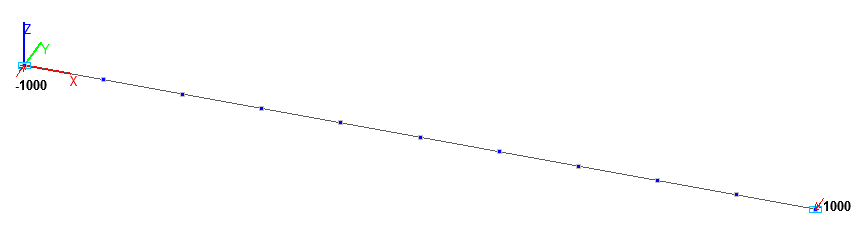
Design model. Bar model
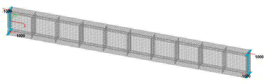
Design model. Reissner-Mindlin shell element model
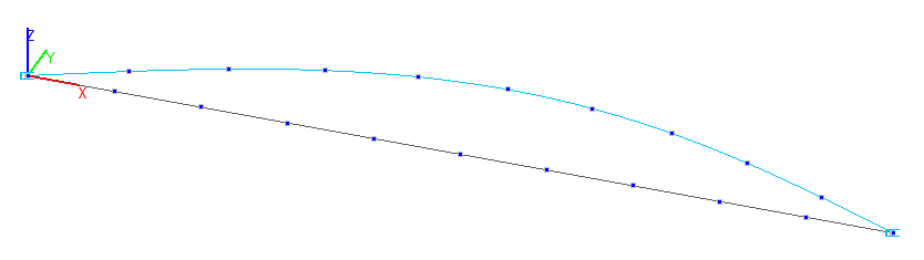
1-st buckling mode. Bar model
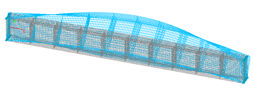
1-st buckling mode. Reissner-Mindlin shell element model
Comparison of solutions:
Critical value of the concentrated bending moments Mcr (kN·m), applied at the ends of the beam simply supported in and out of the bending plane
|
Design model |
Theory |
SCAD |
Deviation, % |
|---|---|---|---|
|
Bar |
1493 |
1,510993∙1000= 1511 |
1,19 |
|
Reissner-Mindlin shell element |
1493 |
1, 545837∙1000= 1546 |
3,52 |
Notes: In the analytical solution the critical value of the concentrated bending moments Mcr, corresponding to the moment of buckling of the simply supported beam can be determined according to the following formula:
\[ M=\frac{\pi \cdot \sqrt {E\cdot I_{z} \cdot G\cdot I_{x} } }{L}\cdot \chi \quad \chi =\sqrt {1+\frac{\pi^{2}}{L^{2}}\cdot \frac{E\cdot I_{\omega } }{G\cdot I_{x} }} \quad G=\frac{E}{2\cdot \left( {1+\nu } \right)} \]
\( I_{z} =\frac{h_{w} \cdot t_{w}^{3}}{12}+2\cdot \frac{b_{f}^{3}\cdot t_{f} }{12} \) – minimum bending inertia moment (out of the moment plane);
\( I_{\omega } =\frac{h_{w}^{2}\cdot b_{f}^{3}\cdot t_{f} }{24} \) – sectorial constrained torsional inertia moment;
\( I_{x} =2\cdot k_{f} \cdot b_{f} \cdot t_{f}^{3}+k_{w} \cdot h_{w} \cdot t_{w}^{3} \) – free torsional inertia moment, where:
\[ k_{f} =\frac{1}{3}\cdot \left\{ {1-\frac{192}{\pi^{5}}\cdot \frac{t_{f} }{b_{f} }\cdot \sum\limits_{n=1}^\infty {\left[ {\sin^{2}\left( {\frac{n\cdot \pi }{2}} \right)\cdot \frac{1}{n^{5}}\cdot th\left( {\frac{n\cdot \pi \cdot h}{2\cdot b}} \right)} \right]} } \right\}, \] \[ k_{w} =\frac{1}{3}\cdot \left\{ {1-\frac{192}{\pi^{5}}\cdot \frac{t_{w} }{h_{w} }\cdot \sum\limits_{n=1}^\infty {\left[ {\sin^{2}\left( {\frac{n\cdot \pi }{2}} \right)\cdot \frac{1}{n^{5}}\cdot th\left( {\frac{n\cdot \pi \cdot h}{2\cdot b}} \right)} \right]} } \right\} \]