Static Analysis of Stress-Strain State of a Building Taking into Account Genetic Nonlinearity
Objective: Comparison of the results of the calculations of the stress-strain state of a multi-storey building taking into account genetic nonlinearity performed by SCAD and ANSYS.
Initial data file: Test-01.MPR
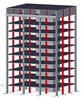
Problem formulation: Design model – 11-storey building fragment rectangular in plan — spatial model consisting of columns, walls, piers, floor slabs on the rigid subgrade (all linear and angular nodal degrees of freedom are constrained). The model is subjected to the uniformly distributed load (1,5 t/m2) applied to all floor slabs.
References: O.V. Kabantsev, Verification of calculation technology “Mounting” from software complex SCAD, International Journal for Computational Civil and Structural Engineering , 2011, 7 (3), 103-109.
Initial data:
Physical properties – material of elements of the design model: concrete of the compressive strength class В25; elastic modulus E = 3 106 t/m2 ; Poisson’s ratio ν = 0,2.
Geometric properties:
Storey height – 3 m,
Column spacing – 7 m along X and 6 m along Y,
Column section – 50×50 cm.
Floor slab thickness – 20 cm
Wall and pier thickness – 40 cm, pier width – 100 cm.
Boundary conditions: columns, piers and walls are clamped in the plane z = 0 m
Loads:
1) Vertical pressure on the floor slabs q1 = 1,5 t/m2 is applied to the newly erected fragments-storeys;
2) Vertical pressure on the floor slabs q2 = 1 t/m2 is applied after the erection of the entire building.
Finite element model:
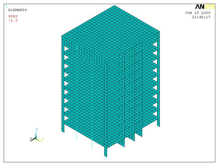
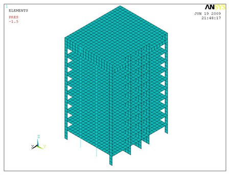
ANSYS
Slabs, walls and piers are modeled by shell finite elements of the SHELL63 type, columns are modeled by beam finite elements of the BEAM44 type.
Stage 1. Resetting the stiffness of all FE to zero (the “element death” function), except for the 1-st floor, and constraining all nodes not belonging to the elements of the 1-st floor in the directions of all degrees of freedom with the application of the load q1 to the slab of the 1-st floor and the subsequent SSS analysis;
Stage 2. Restoring the previous stiffness of the FE (the “element birth” function) of the 2-nd floor and removing the constraints of the nodes belonging to the elements of the 2-nd floor in the directions of all degrees of freedom with the application of the load q1 to the slab of the 2-nd floor and the subsequent SSS analysis;
…….
Stage 11. Restoring the previous stiffness of the FE (the “element birth” function) of the 11-th floor and removing the constraints of the nodes belonging to the elements of the 11-th floor in the directions of all degrees of freedom with the application of the load q1 to the slab of the 11-th floor (roof) and the subsequent SSS analysis;
Stage 12. Application of the load q2 to all floor slabs of the building with the subsequent SSS analysis.
Nodes not belonging to the “born” elements are constrained in order to fix the structural elements of the building at the design elevations to take into account the actual building erection process.
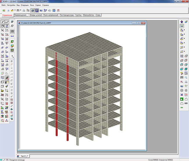
SCAD
Slabs, walls and piers are modeled by shell finite elements of type 44, columns are modeled by bar elements of general type 5.
The dimension of the complete model is 5608 nodes and 5456 finite elements.
Modeling of the building erection process consists of the following stages:
Stage 1. Selection of the set of elements at the level of the 1-st floor which are considered at the stage No.1 with the application of the load q1 to the slab of the 1-st floor and the subsequent SSS analysis;
Stage 2. Selection of the set of elements at the level of the 1-2-nd floors which are considered at the stage No.2 with the application of the load q1 to the slabs included in the 2-nd stage and the subsequent SSS analysis;
…………
Stage 11. Selection of the set of elements at the level of the 1-11-th floors which are considered at the stage No.11 with the application of the load q1 to the slabs included in the 11-th stage and the subsequent SSS analysis;
Stage 12. Application of the load q2 to all floor slabs of the building with the subsequent SSS analysis.
|
|
|
|
General view of the ANSYS design model. |
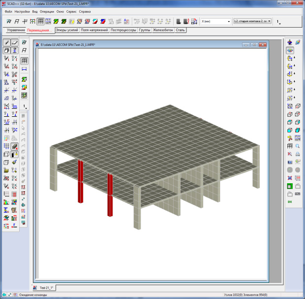
General view of the SCAD design model. |

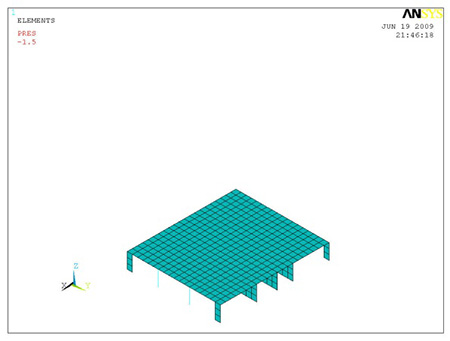
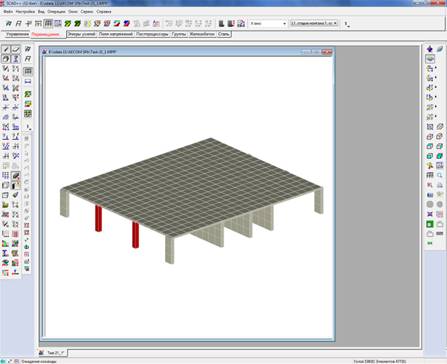
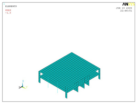
ANSYS and SCAD design models for different calculation stages
|
Stage No. |
ANSYS |
SCAD |
|---|---|---|
|
1 |
|
|
|
2 |
|
|
|
11 |
|
|
|
12 |
|
|
Comparison of solutions:
|
Parameter |
Accounting for the 12 erection stages |
Deviations, % |
|
|
ANSYS |
SCAD |
||
|
Maximum vertical displacement, mm |
-24,8 |
-24,19 |
2,46 |
|
Longitudinal force in a column (1st floor), t |
-870,6 |
-865,1 (FE 386) |
0,63 |
|
Longitudinal force in a column (10th floor), t |
-3,2 |
-2,99 (FE 4679) |
6,56 |