Strength and Stiffness Analysis of Main Beams of Complex Stub Girder Systems
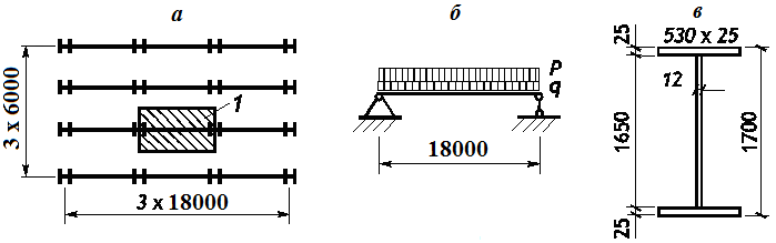
a – floor plan; b – design model of the main beam; c – beam section;
1 – load area
Objective: Check the mode for the beam analysis in the “Steel” postprocessor of SCAD
Task: Select a welded I-beam for the main beams with a span of 18 m in a normal stub girder system. The top chord of the main beams is restrained by the stringers arranged with a spacing of 1 m.
Source: Steel Structures: Student Handbook / [Kudishin U.I., Belenya E.I., Ignatieva V.S and others] - 13-th ed. rev. - M.: Publishing Center "Academy", 2011. p. 192.
Compliance with the codes: SNiP II-23-81*, SP 16.13330.2011, DBN B.2.6-163:2010.
Initial data file:
3.4 Beam_Example_3.4.spr;
report – 3.4 Beam_Example_3.4.doc
Initial data:
| а = 6 м | Spacing of main beams; |
| g1 = 1,16 kN/m2 | Weight of the floor plate and stringers; |
| p = 20 kN/m2 | Temporary (live) load; |
| qн = 127,099 kN/m | Total characteristic load on the beam; |
| q1 = 1,05*1,16 kN/m2 * 6 m*1,02 = 7,454 kN/m | Design permanent load (coefficient 1,02 allows for the self-weight of the main beam); |
| q2 = 1,2*20 kN/m2 * 6 m = 144,0 kN/m | Design live load; |
| l = 18 m | Main beam span; |
| Ry = 23 kN/cm2 Rs = 0,58*23=13,34 kN/cm2 |
Steel grade C255 with thickness t>20 mm; |
| [ f ] = l/400 = 45 mm | Limit deflection; |
| bp×tp = 530×20 mm | Section of the bearing stiffener; |
| kp = 6 mm | Fillet weld leg in a welded connection between a bearing stiffener and a beam; |
| γc = 1 | Service factor; |
| Wy = 27153,85 cm3 | Geometric properties for a welded I-section with flanges 530×25 mm |
| Iy = 2308077,083 cm4 | and a web 1650×12 mm; |
| Sy = 15180,625 cm3. |
SCAD Results. STEEL Postprocessor:
[Element No 3] Forces
|
N Max. 0 T
Max. 0 T |
My
Max. 625,27 T*m |
Mz Max. 0 T*m
Max. 0 T*m |
|
Mk Max. 0 T*m
Max. 0 T*m |
Qz Max. 69,47 T
Max. 0 T |
Qy Max. 0 T
Max. 0 T |
|
|
Length of the bar 4,5 m |
|


[Element No. 3] Deflections
|
X
|
Y
|
Z
Max. -43,54 mm |
|
|
Length of the bar 4,5 m |
|


Analysis complies with SNiP II-23-81*
Structural member main beam
Steel: C255
Member length 18 m
Limit slenderness for members in compression: 180
Limit slenderness for members in tension: 300
Service factor 1
Importance factor 1
Effective length factor XoZ -- 1
Effective length factor XoY -- 1
Length between out-of-plane restraints 1 m
Section

|
Results |
Check |
Utilization factor |
|---|---|---|
|
Sec.5.12 |
Strength under action of bending moment My |
0,98 |
|
Sec.5.12,5.18 |
Strength under action of lateral force Qz |
0,56 |
|
Sec.5.24,5.25 |
Strength under combined action of longitudinal force and bending moments, no plasticity |
0,98 |
|
Sec.5.15 |
Stability of in-plane bending |
0,98 |
|
Sec.6.15,6.16 |
Limit slenderness in XoY plane |
0,52 |
|
Sec.6.15,6.16 |
Limit slenderness in XoZ plane |
0,08 |
Utilization factor 0,98 - Strength under action of bending moment My
Manual calculation (SNiP II-23-81*)
1. Maximum bending moment and shear force acting in the design sections of the beam:
\[ M_{\max } =\frac{q_{\Sigma } l^{2}}{8}=\frac{\left( {7,454+144} \right)\cdot 18,0^{2}}{8}=6133,887 \quad kNm. \] \[ Q_{\max } =\frac{q_{\Sigma } l}{2}=\frac{\left( {7,454+144} \right)\cdot 18,0}{2}=1363,086 \quad kN. \]
2. Necessary beam section modulus:
\[ W_{nes} =\frac{M_{\max } }{R_{y} \gamma_{c} }=\frac{6133,887\cdot 100}{23}=26669,074 \quad cm^{3}. \]
3. Maximum tangential stresses in the support section of the beam:
\[ \tau_{\max } =\frac{Q_{\max } S_{y} }{I_{y} t_{w} }=\frac{1363,086\cdot 15180,625}{2308077,083\cdot 1,2}=7,471 \quad kN/cm^{2}. \]
4. Maximum deflection occurring in the middle of the beam span:
\[ f_{\max } =\frac{5}{384}\cdot \frac{q_{н} l^{4}}{EI_{y} }=\frac{5}{384}\cdot \frac{127,099\cdot 18,0^{4}}{2,06\cdot 10^{5}\cdot 10^{3}\cdot 2308077,083\cdot 10^{-8}}=36,539 \quad mm. \]
5. Conditional limit slenderness of the compressed beam chord:
\[ \bar{{\lambda }}_{ub} =0,35+0,0032\frac{b_{f} }{t_{f} }+\left( {0,76-0,02\frac{b_{f} }{t_{f} }} \right)\frac{b_{f} }{h_{f} }=0,35+0,0032\frac{530}{25}+\left( {0,76-0,02\frac{530}{25}} \right)\frac{530}{1675}=0,524. \]
6. Conditional actual slenderness of the compressed beam chord:
\( \bar{{\lambda }}_{b} =\frac{l_{ef} }{b_{f} }\sqrt {\frac{R_{y} }{E}} =\frac{1000}{530}\sqrt {\frac{230}{2,06\cdot 10^{5}}} =0,063<\bar{{\lambda }}_{ub} =0,524 \) – the stability check is not required.
Comparison of solutions:
|
Factor |
Manual calculation |
SCAD |
Deviation, % |
|---|---|---|---|
|
Strength under action of lateral force |
7,471/13,34 = 0,56 |
0,56 |
0,0 |
|
Strength under action of bending moment |
26669,074/27153,85=0,982 |
0,982 |
0,0 |
|
Stability of in-plane bending under moment |
– |
0,982 |
0,0 |
|
Maximum deflection |
36,539/45 = 0,812 |
43,54/1,1916/45= 0,812 |
0,0 |
Comments:
The check for the stability of in-plane bending of the beam was performed in the computer-aided calculation according to the codes at φb = 1,0.