Simply Supported Beam on the Elastic Horizontal Subgrade Subjected to a Vertical Uniformly Distributed Load, Concentrated Vertical Force and Bending Moment

Objective: Determination of the stress-strain state of a simply supported beam on the elastic horizontal subgrade subjected to a vertical uniformly distributed load, concentrated force and bending moment.
Initial data files:
|
File name |
Description |
|---|---|
|
Design model – bar elements on the elastic subgrade |
|
|
Design model – bar elements on elastic supports in the form of elements of constraints of finite rigidity of type 51 |
Problem formulation: The simply supported beam on the elastic horizontal subgrade with the stiffness k constant along the length is subjected to a vertical uniformly distributed load P, concentrated vertical force F, applied in the middle of the span (point D) and concentrated bending moments -C and C, applied at the edges (points A and B). Determine the vertical displacement Z in the middle of the beam span (point D), rotation angles UY of the beam edges (points A and B), as well as the bending moment M in the middle of the beam span and the shear force Q at the edge of the beam.
References: M. Courtand et P. Lebelle, Formulaire du beton arme, t.2, Paris, Eyrolles,1976, p. 385.
Initial data:
| E = 2.1∙1011 Pa | - elastic modulus; |
| l = 0.5∙π∙(10.0)0.5 = 4.967294133 m | - beam length; |
| b = 1.0 m | - beam width; |
| Iy = 1.0∙10-4 m4 | - cross-sectional moment of inertia of the beam; |
| kz = 8.4∙105 N/m3 | - subsoil parameter; |
| P = 5.0∙103 N/m | - value of the vertical uniformly distributed load; |
| F = 1.0∙104 N | - value of the concentrated vertical force; |
| C = 1.5∙104 N∙m | - value of the concentrated bending moment. |
Finite element model: Two variants of the design model are considered.
Variant 1:
Design model – grade beam / plate, 24 bar elements of type 3 on the elastic subgrade directed along the Z1 axis of the local coordinate system. Boundary conditions are provided by imposing constraints in the direction of the degree of freedom Z for roller support nodes. Number of nodes in the design model – 25.
Variant 2:
Design model – grade beam / plate, 24 bar elements of type 3 on the elastic supports in the form of 25 elements of constraints of finite rigidity of type 51 directed along the Z axis of the global coordinate system. Stiffness of intermediate elastic supports: kz∙b∙l/24 = 173855 N/m, stiffness of end elastic supports: 0.5∙kz∙b∙l/12 = 86928 N/m. Boundary conditions are provided by imposing constraints in the direction of the degree of freedom Z for roller support nodes. In order to prevent the dimensional instability of the system, a constraint in the direction of the degree of freedom UX is imposed along the beam symmetry axis and the minimum torsional stiffness of the beam is introduced GIx = 1.0 N∙m2. Number of nodes in the design model – 25.
Results in SCAD
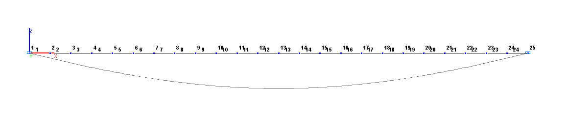
Design and deformed models. Variant 1
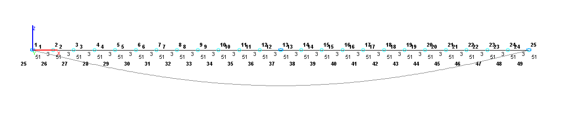
Design and deformed models. Variant 2
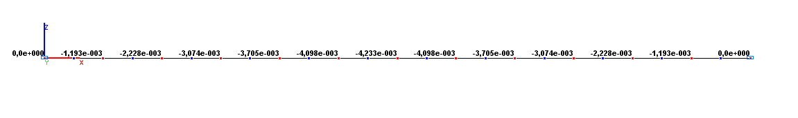
Values of vertical displacements Z (m) for the design model according to variant 1
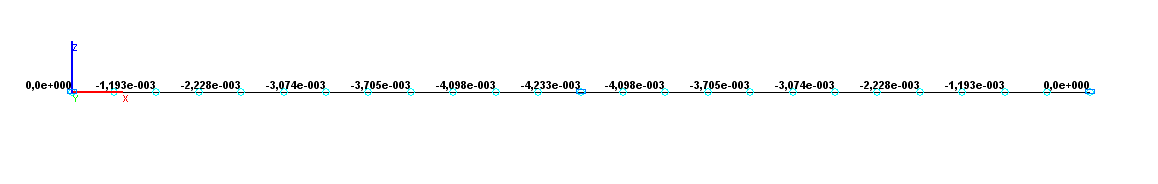
Values of vertical displacements Z (m) for the design model according to variant 2
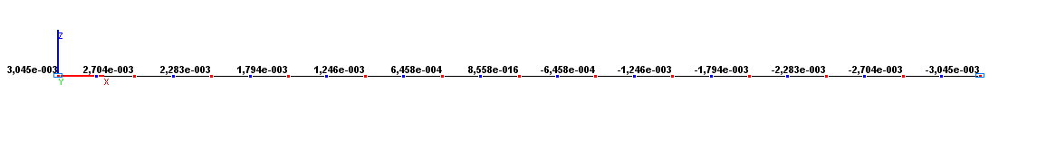
Values of rotation angles UY (rad) for the design model according to variant 1
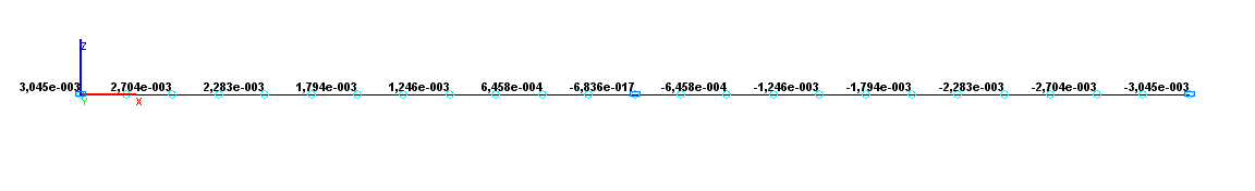
Values of rotation angles UY (rad) for the design model according to variant 2
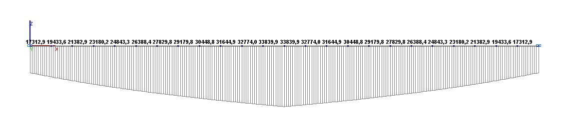
Values of bending moments M (N∙m) for the design model according to variant 1
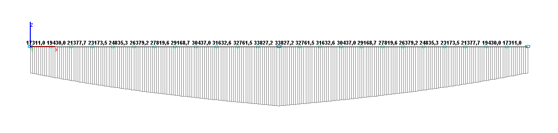
Values of bending moments M (N∙m) for the design model according to variant 2
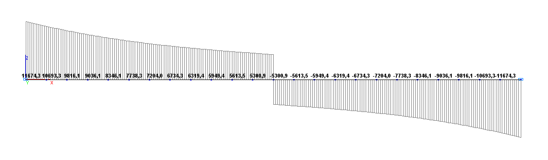
Values of shear forces Q (N) for the design model according to variant 1
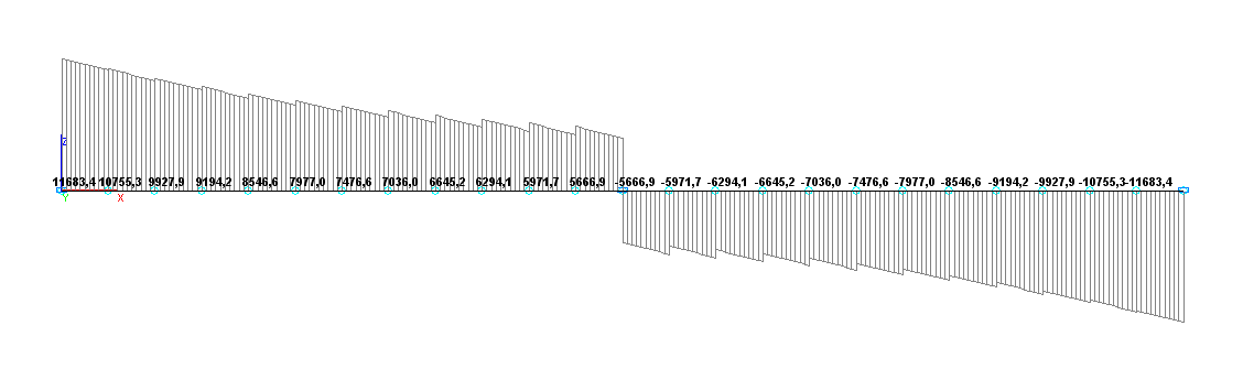
Values of shear forces Q (N) for the design model according to variant 2
Comparison of solutions:
|
Parameter |
Theory |
SCAD DM according to variant 1 |
Deviations, % |
SCAD DM according to variant 2 |
Deviations, % |
|---|---|---|---|---|---|
|
Vertical displacement ZD, m |
-4.233∙10-3 |
-4.233∙10-3 |
0.00 |
-4.233∙10-3 |
0.00 |
|
Rotation angle UYA, rad |
3.045∙10-3 |
3.045∙10-3 |
0.00 |
3.045∙10-3 |
0.00 |
|
Bending moment MD, N∙m |
33840.0 |
33839.9 |
0.00 |
33827.2 |
0.04 |
|
Shear force QA, N |
11674.0 |
11674.3 |
0.00 |
11683.4 |
0.08 |