Sequential Erection of a Steel Reinforced Concrete Single-Span Beam
Objective: Determination of the deflections of the steel reinforced concrete single-span beam for the erection stages.
Problem formulation: The erection of the steel reinforced concrete single-span beam is performed in the following order:
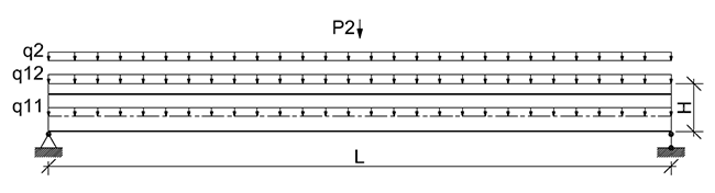
- A steel I-beam is installed on the supports, the formwork for the reinforced concrete slab is arranged on the props from the bottom chord of the beam, the reinforcement cage is installed on the formwork, and the monolithic concrete is laid in the first erection stage. The steel beam is subjected to the load from the self-weight q11 and from the weight of the fresh concrete q12 at this stage.
- The formwork is dismantled, and the reinforced concrete slab starts to bend across the steel beam in the second erection stage.
- The serviceability loads from the weight of the roof structure q2 and the transport load P2 are applied to the steel reinforced concrete beam in the third erection stage.
Determine the maximum deflections of the steel reinforced concrete beam in the first w1 and third w2 erection stages.
Initial data file: Wiring_Girder.MPR
Initial data:
| Est = 2.1·106 kgf/cm2 | - elastic modulus of the material of the steel beam; |
| Eb = 3.06·105 kgf/cm2 | - elastic modulus of the material of the reinforced concrete slab; |
| υst = 0.3 | - Poisson’s ratio of steel; |
| υb = 0.2 | - Poisson’s ratio of reinforced concrete; |
| L = 1365.0 cm | - steel reinforced concrete beam span length; |
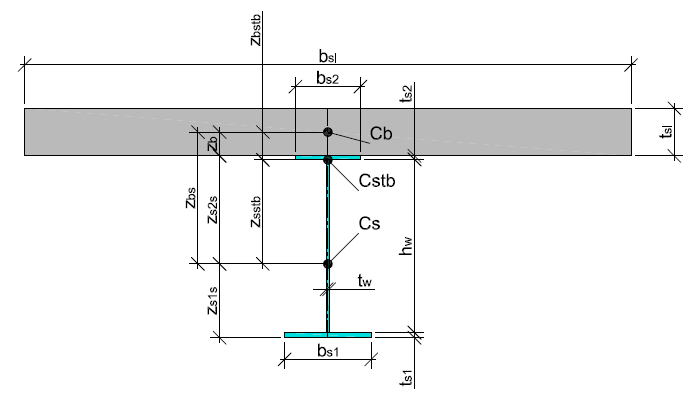
| bs1 = 40.0 cm | - width of the bottom chord of the steel beam; |
| ts1 = 2.4 cm | - thickness of the bottom chord of the steel beamи; |
| bs2 = 30.0 cm | - width of the top chord of the steel beam; |
| ts2 = 1.6 cm | - thickness of the top chord of the steel beam; |
| hw = 80.0 cm | - height of the web of the steel beam; |
| tw = 1.2 cm | - thickness of the web of the steel beam; |
| bsl = 280.0 cm | - width of the reinforced concrete slab; |
| tsl = 22.0 cm | - thickness of the reinforced concrete slab; |
| q11 = 0.2072 t/m | - vertical load from the self-weight of the steel beam uniformly distributed along a line; |
| q12 = 0.6050 t/m2 | - vertical load from the self-weight of the reinforced concrete slab uniformly distributed over an area; |
| q2 = 0.3770 t/m2 | - vertical load from the self-weight of the roof structure uniformly distributed over an area and applied to the reinforced concrete slab; |
| P2 = 39.60 t/m | - vertical transport load uniformly distributed along a line. |
Finite element model: Design model – general type system, elements of the steel beam – 68 bar elements of type 5, elements of the reinforced concrete slab – 952 shell elements of type 44, elements of the joint between the steel beam and the reinforced concrete slab – 69 elements of type 100, elements of the formwork props – 1035 elements of type 100. The spacing of the finite element mesh of the steel beam along the longitudinal axis is 0.2 m. The spacing of the finite element mesh of the reinforced concrete slab in the longitudinal and transverse directions is 0.2 m. The node of the left end of the beam is constrained in the directions of the degrees of freedom X,Y, Z, UX. The node of the right end of the beam is constrained in the directions of the degrees of freedom Y, Z, UX. Number of nodes in the design model – 1173. Elements of the steel beam, elements of the reinforced concrete slab with the reduced elastic modulus Eb∙10-3, elements of the joint and elements of the props are included in the first erection stage. Elements of the steel beam, elements of the reinforced concrete slab with the normal elastic modulus Eb and elements of the joint are included in the second and third erection stages. The loads q11 and q12 of the accumulated loading q1 are acting in all stages. The loads q2 and P2 of the independent loading q2 are acting in the third erection stage.
Results in SCAD:
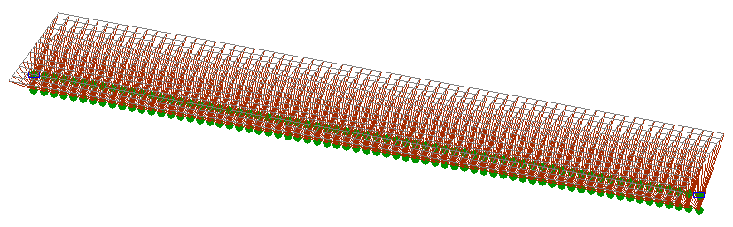
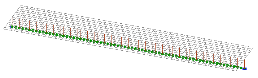
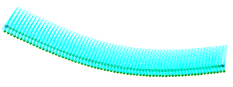
Design models in the first, second and third erection stages
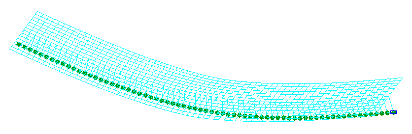
Deformed models in the first and third erection stages
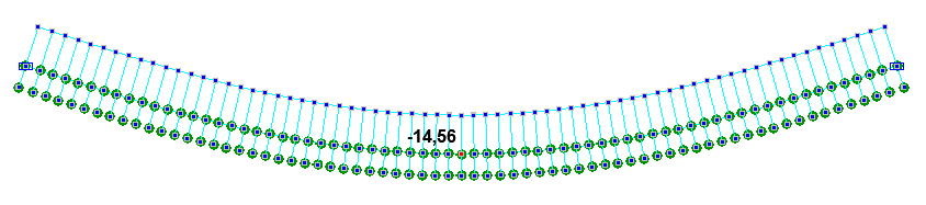
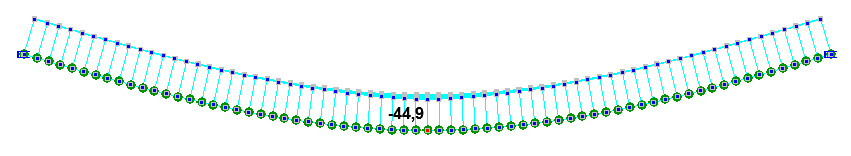
Deflections in the first w1 and third w2 erection stages (mm)
Comparison of solutions:
|
Parameter |
Theory |
SCAD |
Deviations, % |
|---|---|---|---|
|
Maximum deflection of the steel reinforced concrete beam in the first erection stage w1, mm |
-14.75 |
-14,56 |
1.29 |
|
Maximum deflection of the steel reinforced concrete beam in the third erection stage w2, mm |
-44.51 |
-44,90 |
0.88 |
Notes: In the analytical solution the maximum deflections of the steel reinforced concrete beam in the first w1 and third w2 erection stages are determined according to the following formulas:
\[ w_{1} =\frac{5}{384}\cdot \frac{\left( {q_{11} +q_{12} \cdot b_{sl} } \right)\cdot L^{4}}{E_{st} \cdot I_{s} }; \] \[ w_{1} =\frac{5}{384}\cdot \frac{\left( {q_{11} +q_{12} \cdot b_{sl} } \right)\cdot L^{4}}{E_{st} \cdot I_{s} }+\frac{5}{384}\cdot \frac{q_{2} \cdot b_{sl} \cdot L^{4}}{E_{st} \cdot I_{stb} }+\frac{1}{48}\cdot \frac{P_{2} \cdot b_{sl} \cdot L^{3}}{E_{st} \cdot I_{stb} }; \] \[ I_{stb} =I_{s} +A_{s} \cdot z_{sstb}^{2} +\frac{I_{b} }{n_{b} }+\frac{A_{b} }{n_{b} }\cdot z_{bstb}^{2} ;\quad z_{bstb} =z_{bs} -z_{sstb} ;\quad z_{sstb} =\frac{S_{stb} }{A_{stb} }; \] \[ S_{stb} =\frac{A_{b} }{n_{b} }\cdot z_{bs} ;\quad A_{stb} =A_{s} +\frac{A_{b} }{n_{b} };\quad z_{bs} =z_{s2s} +z_{b} ;\quad I_{b} =\frac{b_{sl} \cdot t_{sl} }{12}; \] \[ z_{b} =\frac{S_{b} }{A_{b} };\quad S_{b} =\frac{b_{sl} \cdot t_{sl}^{2} }{2};\quad A_{b} =b_{sl} \cdot t_{sl} ;\quad n_{b} =\frac{E_{st} }{E_{b} }; \] \[ I_{s} =I_{s1s} +I_{ws} +I_{s2s} ;\quad I_{s2s} =I_{s2} +A_{s2} \cdot \left( {t_{s1} +h_{w} +\frac{t_{s2} }{2}-z_{s1s} } \right)^{2}; \] \[ I_{ws} =I_{w} +A_{w} \cdot \left( {t_{s1} +\frac{h_{w} }{2}-z_{s1s} } \right)^{2};\quad I_{s1s} =I_{s1} +A_{s1} \cdot \left( {z_{s1s} -\frac{t_{s1} }{2}} \right)^{2}; \] \[ I_{w} =\frac{t_{w} \cdot h_{w}^{3} }{12};\quad I_{s2} =\frac{b_{s2} \cdot t_{s2}^{3} }{12};\quad I_{s1} =\frac{b_{s1} \cdot t_{s1}^{3} }{12}; \] \[ z_{s2s} =H_{s} -z_{s1s} ;\quad z_{s1s} =\frac{S_{s} }{A_{s} };\quad S_{s} =A_{s1} \cdot \frac{t_{s1} }{2}+A_{w} \cdot \left( {t_{s1} +\frac{h_{w} }{2}} \right)+A_{s2} \cdot \left( {t_{s1} +h_{w} +\frac{t_{s2} }{2}} \right); \] \[ A_{s} =A_{s1} +A_{w} +A_{s2} ;\quad H=H_{s} +t_{sl} ;\quad H_{s} =t_{s1} +h_{w} +t_{s2} ; \] \[ A_{w} =t_{w} \cdot h_{w} ;\quad A_{s2} =b_{s2} \cdot t_{s2} ;\quad A_{s1} =b_{s1} \cdot t_{s1} ; \]