Square Panel of a Flat Slab Rigidly Connected to a Column of a Circular Cross-Section Subjected to a Uniformly Distributed Transverse Load

Objective:
Determine the bending moments in the characteristic points of a square panel of a flat slab rigidly connected to a column of a circular cross-section subjected to a uniformly distributed transverse load.
SCAD version used: 11.3
Initial data file: Flate_plate_Circular_column.spr
Problem formulation:
The square panel of a flat slab rigidly connected to a column of a circular cross-section is subjected to a uniformly distributed transverse load q. Determine the bending moments Mx, My in the characteristic points of the square panel of the flat slab.
References:
S. Timoshenko, S. Woinowsky-Krieger, Theory of Plates and Shells, Moscow, Book House "LIBROKOM", 2009, p. 287-289.
Initial data:
| E = 3.0·107 N/m2 | - elastic modulus, |
| ν = 0.2 | - Poisson’s ratio, |
| h = 0.1 m | - thickness of the panel of the flat slab; |
| a = 2.5 m | - side of the panel of the flat slab; |
| c = 0.1·a = 0.25 m | - radius of the column cross-section; |
| q = 100.0 N/m2 | - value of the uniformly distributed transverse load. |
Finite element model:
Design model – grade beam, plate; elements of the panel of the flat slab – 2412 quadrangular four-node thin plate elements for the calculation according to the Kirchhoff-Love theory of type 20 and 16 triangular three-node thin plate elements for the calculation according to the Kirchhoff-Love theory of type 15; element of the column cross-section – 1 rigid body element of type 100. The spacing of the finite element mesh of the panel of the flat slab in the directions of the axes of the global coordinate system is 0.05 m except for the support contour where the spacing of the finite element mesh in the radial direction is 0.05 m and in the circumferential direction is 11.25°. Internal forces are output along the axes of the global coordinate system. Boundary conditions are provided by imposing constraints in the directions of the degrees of freedom UX for the edges of the panel parallel to the X axis of the global coordinate system, and UY for the edges of the panel parallel to the Y axis of the global coordinate system. The master node of the rigid body of the column is in the center of its cross-section and is restrained in the direction of the degree of freedom Z. Number of nodes in the design model – 2537.
Results in SCAD:
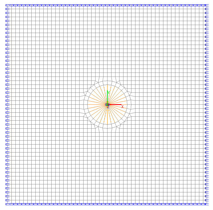

Design model
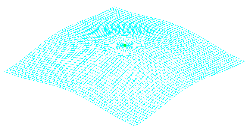
Deformed model
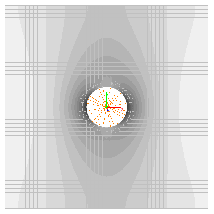
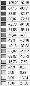
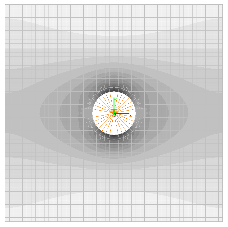
Bending moments Mx, N∙ m/m
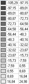
Bending moments My, N∙ m/m
Bending moments Mxy, N∙ m/m
Comparison of solutions:
|
Bending moment |
Panel point |
Theory |
SCAD |
Deviations, % |
|---|---|---|---|---|
|
Mx = My |
x = a/2, y = a/2 |
18.2500 |
17.8300 |
2.30 |
|
Mx |
x = a/2, y = 0 |
24.9375 |
24.9800 |
0.17 |
|
My |
x = a/2, y = 0 |
-10.0625 |
-10.1400 |
0.77 |
|
Mx |
x = c, y = 0 |
-105.1250 |
-105.2900 |
0.16 |
Notes: In the analytical solution the bending moments Mx, My in the characteristic points of the square panel of the flat slab are determined according to the following formulas:
M = β∙q∙a2.
The coefficients β for the calculation of bending moments at c = 0.1∙a and υ = 0.2
|
Bending moment |
Panel point |
β |
|---|---|---|
|
Mx = My |
x = a/2, y = a/2 |
0.0292 |
|
Mx |
x = a/2, y = 0 |
0.0399 |
|
My |
x = a/2, y = 0 |
-0.0161 |
|
Mx |
x = c, y = 0 |
-0.1682 |