Doubly Clamped Beam Subjected to the Transverse Displacement of One of its Ends

Objective: Determination of the stress state of a doubly clamped beam subjected to the transverse displacement of one of its ends.
Initial data file: CS09_v11.3.spr
Problem formulation: The doubly clamped beam of a rectangular cross-section is subjected to a transverse displacement v of one of its ends. Determine the shear force Q and the bending moment M at the displaced end.
References: J. M. Gere and W. Weaver, Jr., Analysis of Framed Structures, New York, D. Van Nostrand Co., 1965.
Initial data:
| E = 3.0·107 Pa | - elastic modulus, |
| L = 80.0 m | - beam length; |
| b = 2.0 m | - width of the beam cross-section; |
| h = 2.0 m | - height of the beam cross-section; |
| v = 1.0 m | - value of the transverse displacement. |
Finite element model: Design model – plane frame, 4 elements of type 2. The spacing of the finite element mesh along the longitudinal axis (along the X axis of the global coordinate system) is 20.0 m. Boundary conditions at the clamped ends are provided by imposing constraints in the directions of the degrees of freedom: X, Z, UY. The action of the given transverse displacement is specified by the displacement of the respective constraint along the Z axis of the global coordinate system. Number of nodes in the design model – 5.
Results in SCAD
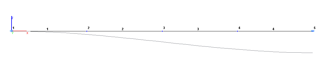
Design and deformed models
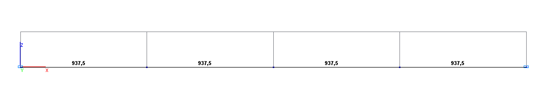
Shear force diagram Q (N)
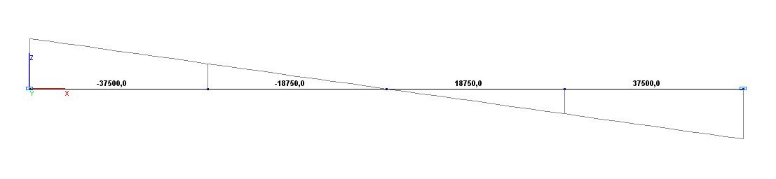
Bending moment diagram М (N∙m)
Comparison of solutions:
|
Parameter |
Theory |
SCAD |
Deviations, % |
|---|---|---|---|
|
Shear force Q at the displaced end, N |
937.5 |
937.5 |
0.00 |
|
Bending moment M at the displaced end, N∙m |
37500.0 |
37500.0 |
0.00 |
Notes: In the analytical solution, the shear force Q and the bending moment M at the displaced end are determined according to the following formulas:
\[ Q=\frac{12\cdot E\cdot I}{L^{3}}; \quad M=\frac{6\cdot E\cdot I}{L^{2}}, where: I=\frac{b\cdot h^{3}}{12}. \]