Calculation of a Simply Supported Rectangular Beam under Lateral Forces
Objective: Check the mode for calculating reinforced concrete structures in the “Reinforced Concrete” postprocessor of SCAD
Task: Check the strength of the oblique section of the beam for the specified reinforcement
References: Guide on designing of concrete and reinforced concrete structures made of heavy-weight concrete (no prestressing) (to SP 52-101-2003), 2005, p. 57-58.
Initial data file:
SCAD 13 SP.spr
report – SCAD 13 SP.doc
Compliance with the codes: SP 52-101-2003.
Initial data:
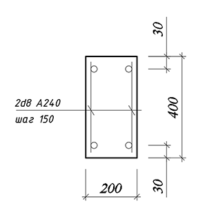
| b×h = 200×400 mm | Section sizes |
| а = 30 mm | Distance to the c.o.g. of tensile reinforcement |
| а/= 30 mm | Distance to the c.o.g. of compressed reinforcement |
| Asw = 101mm2 (2Ø8)Класс бетона В25 | Cross-sectional area of transverse reinforcement |
| sw = 150 mm | Spacing of transverse reinforcement |
| qv = 36 kN/m | Temporary load on the beam |
| qg = 14 kN/m | Permanent load on the beam |
| Q = 100,35 kNm | Lateral force on the support |
| Concrete class В25 | |
| Class of reinforcement 240 |
Results of the SCAD analysis:
|
N Max. 0 kN
Max. 0 kN |
My Max. 0 kN*m
Max. 100,7 kN*m |
Mz
|
|
Mk
|
Qz Max. 100,35 kN
Max. -100,35 kN |
Qy
|
|
|
Length of the bar 4,01 m |
|


Structural group Beam
Structural group Beam. Element No. 1
Importance factor γn = 1
Member type – Flexural
Stress state - Uniaxial bending
|
Coefficients allowing for seismic action |
|
|---|---|
|
Normal sections |
0 |
|
Oblique sections |
0 |
|
Distance to the c.o.g. of reinforcement |
|
|---|---|
|
a1 |
a2 |
|
mm |
mm |
|
30 |
30 |
|
Reinforcement |
Class |
Service factor |
|---|---|---|
|
Longitudinal |
A240 |
1 |
|
Transverse |
A240 |
1 |
Concrete
Concrete type: Heavy-weight
Concrete class: B25
|
Service factor for concrete |
||
|---|---|---|
|
γb1 |
allowance for the sustained loads |
1 |
|
γb2 |
allowance for the failure behavior |
1 |
|
γb3 |
allowance for the vertical position during concreting |
1 |
|
γb4 |
allowance for the freezing/thawing and negative temperatures |
1 |
Humidity of environmental air - 40-75%
Crack resistance
No cracks
Structural group Beam. Element No. 1
Member length 4,01 m
Specified reinforcement
|
Segment |
Reinforcement |
Section |
|
1 |
S1 - 2Ø6 S2 - 2Ø6 Transverse reinforcement along the Z axis 2Ø8, spacing of transverse reinforcement 150 mm Transverse reinforcement along the Y axis 2Ø8, spacing of transverse reinforcement 150 mm
|
|

|
Results |
|||
|---|---|---|---|
|
Segment |
Utilization factor |
Check |
Checked according to SNiP |
|
1 |
0,98 |
Strength for an oblique section |
Sec. 6.2.34, Sec. 3.52,3.71 of the Guide |
Comparison of solutions
|
Check |
Strength of the section |
|
Guide |
100,35/100,69 = 0,997 |
|
SCAD |
0,98 |
|
Deviation, % |
1,7 % |
Comments:
- The strength check of oblique sections is performed by comparing a sum of lateral forces resisted by concrete and stirrups in the oblique section (Qb + Qsw), with a lateral force Q in the oblique section which is determined as a projection on the normal to the longitudinal axis of the element of the resultant of all external forces acting on the element on one side of the considered oblique section (Q = Qmax – q1c). The lateral force in the normal section is taken as Q = 100,35 kN according to the Guide.
- The data on the longitudinal reinforcement has to be specified in SCAD. Since it is not defined in the problem, the following reinforcement is used: class А240, rebars 2Ø6.