Calculation of a Column of a Multi-storey Frame for Load-bearing Capacity under a Lateral Force
Objective: Check the mode for calculating reinforced concrete structures in the “Reinforced Concrete” postprocessor of SCAD
Task: Check the strength of the column section for the specified reinforcement
References: Guide on designing of concrete and reinforced concrete structures made of heavy-weight concrete (no prestressing) (to SP 52-101-2003), 2005, p. 104-105.
Initial data file:
SCAD 34 SP.spr
report – SCAD 34 SP-2003.doc
report – SCAD 34 SP-2012.doc
Compliance with the codes: SP 52-101-2003, SP 63.13330.2012.
Initial data:
Bending moment in the lower support section
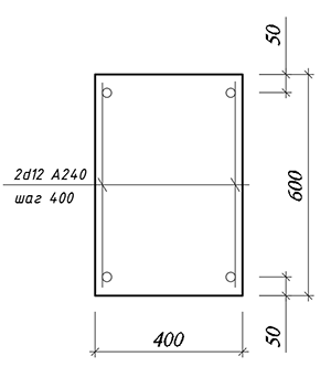
| b×h = 400×600 mm | Section sizes |
| а = 50 mm | Distance to the c.o.g. of tensile reinforcement |
| а/= 50 mm | Distance to the c.o.g. of compressed reinforcement |
| Asw = 226 mm2 (2Ø12) | Cross-sectional area of tensile reinforcement |
| sw = 400 mm | Cross-sectional area of compressed reinforcement |
| l = 3,3 m | Column length |
| Мinf = 250 kNm | |
| Мsup = 350 kNm | Bending moment in the upper support section |
| N = 572 kN | Longitudinal compressive force |
| Concrete class В25 | |
| Class of transverse reinforcement А240 |
Results of the SCAD analysis:
|
N
Max. -572 kN |
My Max. -350 kN*m
Max. 250 kN*m |
Mz Max. 0 kN*m
Max. 0 kN*m |
|
Mk Max. 0 kN*m
Max. 0 kN*m |
Qz
Max. -181,82 kN |
Qy Max. 0 kN
Max. 0 kN |
|
|
Length of the bar 3,3 m |
|


Structural group Column
Spacing of transverse reinforcement is greater than the allowable value (see Sec. 8.3.11 of SP 52-101-2003).
Elements: 1
Importance factor γn = 1
Member type - Member under compression and bending (in tension)
Stress state - Uniaxial bending
Maximum percentage of reinforcement 10
Random eccentricity along Z1 0 mm
Random eccentricity along Y1 0 mm
Structure is statically indeterminate
Effective length factor in the X1OZ1 plane 1
Effective length factor in the X1OY1 plane 1
|
Coefficients allowing for seismic action |
|
|---|---|
|
Normal sections |
0 |
|
Oblique sections |
0 |
|
Distance to the c.o.g. of reinforcement |
|
|---|---|
|
a1 |
a2 |
|
mm |
mm |
|
50 |
50 |
|
Reinforcement |
Class |
Service factor |
|---|---|---|
|
Longitudinal |
A240 |
1 |
|
Transverse |
A240 |
1 |
Concrete
Concrete type: Heavy-weight
Concrete class: B25
|
Service factor for concrete |
||
|---|---|---|
|
γb1 |
allowance for the sustained loads |
1 |
|
γb2 |
allowance for the failure behavior |
1 |
|
γb3 |
allowance for the vertical position during concreting |
1 |
|
γb4 |
allowance for the freezing/thawing and negative temperatures |
1 |
Humidity of environmental air - 40-75%
Crack resistance
No cracks
Structural group Column. Element No. 1
Member length 3,3 m
Specified reinforcement
|
Segment |
Reinforcement |
Section |
|
1 |
S1 - 2Ø6 Transverse reinforcement along the Z axis 2Ø12, spacing of transverse reinforcement 400 mm Transverse reinforcement along the Y axis 2Ø12, spacing of transverse reinforcement 400 mm
|
|

|
Results |
|||
|---|---|---|---|
|
Segment |
Utilization factor |
Check |
Checked according to SNiP |
|
1 |
0,98 |
Strength for an oblique section |
Sec. 6.2.34, Sec. 3.52,3.71 of the Guide |
Comparison of solutions (according to SNiP 52-101-2003):
|
Check |
Strength for an oblique section |
|
Guide |
181,8/184,8 = 0,984 |
|
SCAD |
0,98 |
|
Deviation, % |
0,4 % |