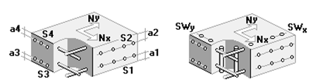
Example of Punching Near the Edge of the Slab
1 – closed design contour No.1, 2 – open design contour No.2, 3 – open design contour No.3.
Punching Analysis of a Flat Monolithic Floor Slab
Objective: Check the Punching mode in the “Reinforced Concrete” postprocessor of SCAD
Task: Verify the correctness of the punching strength analysis of a concrete element under a concentrated force and a bending moment when the load application area is near the edge of the slab.
Compliance with the codes: SNiP 52-101-2003, SP 63.13330.2012.
Initial data file:
SCAD 41 SP-2003.spr,
SCAD 41 SP-2012.spr
report – SCAD 41 SP-2003.doc
report – SCAD 41 SP-2012.doc
Initial data:
| h = 230 mm | Slab thickness |
| h0 = 200 mm | Average effective height of the slab |
| a×b = 500×400 mm | Column section sizes |
| F = 150 кН | Load transferred from the floor slab to the column |
| Msup = 80 kN∙m | Moment in the column section on the upper face of the slab |
| Minf = 90 kN∙m | Moment in the column section on the lower face of the slab |
| x0 = 500 mm | Distance from the center of the column section to the free edge of the slab |
| Concrete class | В25 |
Analytical solution:
In this case it is necessary to check the strength of three contours of the design cross-section:
contour No.1 – closed contour around the column section at a distance of 0,5h0 from the column contour;
contour No.2 – open contour around the column section at a distance of 0,5h0 from the column contour with the extension of the contour to the free edge of the slab;
contour No.3 – open contour around the column section at a distance of 0,5h0 from the column contour (contour of the verification analysis without the consideration of the reinforcement).
- Closed contour No.1:
Lx = Ax + h0 = 500 + 200 = 700 мм = 0,7 м,
Ly = Ay + h0 = 400 + 200 = 600 мм = 0,6 м,
Perimeter of the design contour of the cross-section:
u = 2(Lx + Ly) = 2 (0,7 + 0,6) = 2,6 м.
Area of the design contour of the cross-section:
Ab = uh0 = 2,6 х 0,2 = 0,52 м2.
Ultimate force resisted by concrete:
Fb,ult = RbtAb = 1,05 х103 х 0,52 = 546 kN.
Moment of inertia of the design contour with respect to the X axis passing through its center of gravity:
\[ I_{bx} =2\frac{L_{y}^{3} }{12}+2L_{x} \left( {\frac{L_{y} }{2}} \right)^{2}= \quad 2\frac{0,6^{3} }{12}+2\cdot 0,7\left( {\frac{0,6}{2}} \right)^{2}=\quad 0,162 м^{3}. \]
Section modulus of the design contour of concrete
\[ W_{bx} =\frac{I_{bx} }{y_{\max } }== \quad \frac{0,162}{0,3}=\quad 0,54 м^{2}. \]
Moment of inertia of the design contour with respect to the Y axis passing through its center of gravity:
\[ I_{by} =2\frac{L_{x}^{3} }{12}+2\cdot L_{y} \left( {\frac{L_{x} }{2}} \right)^{2}= \quad 2\frac{0,7^{3} }{12}+2\cdot 0,6\left( {\frac{0,7}{2}} \right)^{2}=\quad 0,204 м^{3}. \]
Section modulus of the design contour of concrete
\[ W_{by} =\frac{I_{by} }{x_{\max } }== \quad \frac{0,204}{0,35}=\quad 0,583 м^{2}. \]
Bending moment which can be resisted by concrete in the design cross-section:
Mbx,ult = RbtWbxh0 = 1,05 х103 х 0,54 х 0,2 = 113,4 кНм.
Mby,ult = RbtWbyh0 = 1,05 х103 х 0,583 х 0,2 = 122,4 кНм.
For SNiP 52-101-2003:
\[ \frac{M_{x} }{M_{bx,ult} }\le \frac{F}{F_{b,ult} }; \quad \frac{M_{y} }{M_{by,ult} }\le \frac{F}{F_{b,ult} } \] \( \frac{M_{y} }{M_{by,ult} }=\frac{85}{122,4}=0,694\le \frac{F}{F_{b,ult} }=\frac{150}{546}=0,275 \) – condition is not met.
Assume
\[ \frac{M_{y} }{M_{by,ult} }=\frac{F}{F_{b,ult} }=0,275 \]
Punching strength of the slab:
\[ K1=\left[ {\frac{F}{F_{b,ult} }} \right.+\left. {\frac{M_{x} }{M_{bx,ult} }+\frac{M_{y} }{M_{by,ult} }} \right]\le 1,0 \]
\[ К1 = 0,275 + 0 + 0,275 = 0,55 \]
For SP 63.13330.2012:
\[ \frac{M_{x} }{M_{bx,ult} } + \frac{M_{y} }{M_{by,ult} } \le 0,5 \frac{F}{F_{b,ult} } \] \( \frac{M_{y} }{M_{by,ult} }=\frac{85}{122,4}=0,694\le 0,5\frac{F}{F_{b,ult} }=\frac{150}{546}=0,5\cdot 0,275=0,1375\quad \) – condition is not met.
Assume
\[ \frac{M_{y} }{M_{by,ult} }=\frac{F}{F_{b,ult} }=0,1375 \]
Punching strength of the slab:
\[ K1=\left[ {\frac{F}{F_{b,ult} }} \right.+\left. {\frac{M_{x} }{M_{bx,ult} }+\frac{M_{y} }{M_{by,ult} }} \right]\le 1,0 \] \[ К1 = 0,275 + 0 + 0,1375 = 0,413 \]
Open contour No.2:
Lx =Ax +h0 + 150 = 500 + 200 + 150 = 850 mm = 0,85 m,
Ly =Ay +h0 = 400 + 200 = 600 mm = 0,6 m,
Perimeter of the design contour of the cross-section:
u = 2Lx + Ly = 2х0,85 + 0,6 = 2,3 m.
Area of the design contour of the cross-section:
Ab = uh0 = 2,3 х 0,2 = 0,46 m2.
X coordinate of the center of gravity of the open contour with respect to the left edge of the slab:
\[ X=\frac{425\cdot 850\cdot 2+850\cdot 600}{850\cdot 2+600}=535,869 мм \]
Ultimate force resisted by concrete:
Fb,ult = RbtAb = 1,05 х103 х 0,46 = 483 kN.
Moment of inertia of the design contour with respect to the X axis passing through its center of gravity:
\[ I_{bx} =\frac{L_{y}^{3} }{12}+2L_{x} \left( {\frac{L_{y} }{2}} \right)^{2}= \quad \frac{0,6^{3} }{12}+2\cdot 0,85\left( {\frac{0,6}{2}} \right)^{2}=\quad 0,171 м^{3}. \]
Section modulus of the design contour of concrete
\[ W_{bx} =\frac{I_{bx} }{y_{\max } }= \quad \frac{0,171}{0,3}=\quad 0,57 м^{2}. \]
Moment of inertia of the design contour with respect to the Y axis passing through its center of gravity:
\[ I_{by} =2\frac{L_{x}^{3} }{12}+2L_{x} (0,075+0,035869)^{2}+L_{y} \left( {0,35-0,035869} \right)^{2}= 2\frac{0,85^{3} }{12}+2\cdot 0,85(0,075+0,035869)^{2}+0,6\left( {0,35-0,035869} \right)^{2}=0,183 м^{3}. \]
Section modulus of the design contour of concrete
\[ W_{by} =\frac{I_{by} }{x_{\max } }= \quad \frac{0,183}{0,535869}=\quad 0,341 м^{2}. \]
Bending moment which can be resisted by concrete in the design cross-section:
Mbx,ult = RbtWbxh0 =1,05 х103 х 0,57 х 0,2 = 119,7 kNm.
Mby,ult = RbtWbyh0 = 1,05 х103 х 0,341 х 0,2 = 71,6 kNm.
My = My - Fe0 = 85 – 150х0,035869 = 85 – 5,38 = 79,62 kNm.
For SNiP 52-101-2003:
\[ \frac{M_{x} }{M_{bx,ult} }\le \frac{F}{F_{b,ult} }; \quad \frac{M_{y} }{M_{by,ult} }\le \frac{F}{F_{b,ult} } \] \( \frac{M_{y} }{M_{by,ult} }=\frac{79,62}{71,6}=1,112\le \frac{F}{F_{b,ult} }=\frac{150}{483}=0,311 \) – condition is not met.
Assume
\[ \frac{M_{y} }{M_{by,ult} }=\frac{F}{F_{b,ult} }=0,311 \]
Punching strength of the slab:
\[ K1=\left[ {\frac{F}{F_{b,ult} }} \right.+\left. {\frac{M_{x} }{M_{bx,ult} }+\frac{M_{y} }{M_{by,ult} }} \right]\le 1,0 \] \[ К1 = 0,311+0+0,311 = 0,622 \]
For SP 63.13330.2012:
\[ \frac{M_{x} }{M_{bx,ult} }+\frac{M_{y} }{M_{by,ult} }\le 0,5\frac{F}{F_{b,ult} } \] \( \frac{M_{y} }{M_{by,ult} }=\frac{79,62}{71,6}=1,112\le 0,5\frac{F}{F_{b,ult} }=\frac{150}{483}=0,5\cdot 0,311=0,155 \) – condition is not met.
Assume
\[ \frac{M_{y} }{M_{by,ult} }=\frac{F}{F_{b,ult} }=0,155 \]
Punching strength of the slab:
\[ K1=\left[ {\frac{F}{F_{b,ult} }} \right.+\left. {\frac{M_{x} }{M_{bx,ult} }+\frac{M_{y} }{M_{by,ult} }} \right]\le 1,0 \] \[ К1 = 0,311 + 0 + 0,155 = 0,466 \]
Open contour No.3:
Lx = Ax + 1,5h0 + 250 = 500 +1,5х200 + 250 = 1050 mm = 1,05 m,
Ly = Ay + 2·1,5h0 = 400 + 2х1,5х200 = 1000 mm = 1,0 m,
Perimeter of the design contour of the cross-section:
u = 2Lx + Ly = 2х1,05 + 1,0 = 3,1 m.
Area of the design contour of the cross-section:
Ab = uh0 = 3,1 х 0,2 = 0,62 m2.
X coordinate of the center of gravity of the open contour with respect to the left edge of the slab:
\[ X=\frac{525\cdot 1050\cdot 2+1050\cdot 1000}{1050\cdot 2+1000}=694,355 мм \]
Ultimate force resisted by concrete:
Fb,ult = RbtAb = 1,05 х103 х 0,62 = 651 kN.
Moment of inertia of the design contour with respect to the X axis passing through its center of gravity:
\[ I_{bx} =\frac{L_{y}^{3} }{12}+2L_{x} \left( {\frac{L_{y} }{2}} \right)^{2}= \quad \frac{1,05^{3} }{12}+2\cdot 1,05\left( {\frac{1,0}{2}} \right)^{2}=\quad 0,608 м^{3}. \]
Section modulus of the design contour of concrete
\[ W_{bx} =\frac{I_{bx} }{y_{\max } }= \quad \frac{0,608}{0,5}=\quad 1,217 м^{2}. \]
Moment of inertia of the design contour with respect to the Y axis passing through its center of gravity:
\[ I_{by} =2\frac{L_{x}^{3} }{12}+2L_{x} (0,194355-0,025)^{2}+L_{y} \left( {1,05-0,694355} \right)^{2}= 2\frac{1,05^{3} }{12}+2\cdot 1,05(0,194355-0,025)^{2}+1,0\left( {1,05-0,694355} \right)^{2}=0,38 м^{3}. \]
Section modulus of the design contour of concrete
\[ W_{by} =\frac{I_{by} }{x_{\max } }= \quad \frac{0,38}{0,694355}=\quad 0,547 м^{2}. \]
Bending moment which can be resisted by concrete in the design cross-section:
Mbx,ult = RbtWbxh0 = 1,05 х103 х 1,217 х 0,2 = 255,57 kNm.
Mby,ult = RbtWbyh0 = 1,05 х103 х 0,547 х 0,2 = 114,87 kNm.
My = My - Fe0 = 85 – 150х0,194355 = 85 – 29,15 = 55,85 kNm.
For SNiP 52-101-2003:
\[ \frac{M_{x} }{M_{bx,ult} }\le \frac{F}{F_{b,ult} }; \quad \frac{M_{y} }{M_{by,ult} }\le \frac{F}{F_{b,ult} } \] \( \frac{M_{y} }{M_{by,ult} }=\frac{79,62}{71,6}=1,112\le \frac{F}{F_{b,ult} }=\frac{150}{483}=0,311 \) – condition is not met.
Assume
\[ \frac{M_{y} }{M_{by,ult} }=\frac{F}{F_{b,ult} }=0,311 \]
Punching strength of the slab:
\[ K1=\left[ {\frac{F}{F_{b,ult} }} \right.+\left. {\frac{M_{x} }{M_{bx,ult} }+\frac{M_{y} }{M_{by,ult} }} \right]\le 1,0 \] \[ К1 = 0,311+0+0,311 = 0,622 \]
For SP 63.13330.2012:
\[ \frac{M_{x} }{M_{bx,ult} }+\frac{M_{y} }{M_{by,ult} }\le 0,5\frac{F}{F_{b,ult} } \] \( \frac{M_{y} }{M_{by,ult} }=\frac{79,62}{71,6}=1,112\le 0,5\frac{F}{F_{b,ult} }=\frac{150}{483}=0,5\cdot 0,311=0,155 \) – condition is not met.
Assume
\[ \frac{M_{y} }{M_{by,ult} }=\frac{F}{F_{b,ult} }=0,155 \]
Punching strength of the slab:
\[ K1=\left[ {\frac{F}{F_{b,ult} }} \right.+\left. {\frac{M_{x} }{M_{bx,ult} }+\frac{M_{y} }{M_{by,ult} }} \right]\le 1,0 \] \[ К1 = 0,23 + 0 + 0,115 = 0,345
\]
Results of the SCAD analysis:
Node No. 5
Importance factor γn = 1
Concrete
Concrete type: Heavy-weight
Concrete class: B25
|
Service factor for concrete |
||
|---|---|---|
|
γb1 |
allowance for the sustained loads |
1 |
|
γb2 |
allowance for the failure behavior |
1 |
|
γb3 |
allowance for the vertical position during concreting |
1 |
|
γb4 |
allowance for the freezing/thawing and negative temperatures |
1 |
|
Distance to the c.o.g. of reinforcement |
|||
|---|---|---|---|
|
a1 |
a2 |
a3 |
a4 |
|
mm |
mm |
mm |
mm |
|
30 |
30 |
0 |
0 |
Results
Design case – edge column
Length of the upper base of the bearing pyramid - 1800 mm
Length of the lower base of the bearing pyramid - 2300 mm
Comparison of solutions (according to SNiP 52-101-2003)
|
Checked according to SNiP |
Check |
Utilization factor |
|---|---|---|
|
Sec.6.2.49 |
Strength without the consideration of the reinforcement |
0,62 |
|
Check |
punching strength of an unclosed concrete element under a concentrated force and bending moments (including additional ones caused by the eccentric application of a force with respect to the punched contour) with their vectors along X,Y-axes (load application area is near the edge of the slab) |
|
Analytical solution |
0,622 |
|
SCAD |
0,62 |
|
Deviation, % |
0,1 % |
Comparison of solutions (according to SP 63.13330.2012)
|
Checked according to SP |
Check |
Utilization factor |
|---|---|---|
|
Sec.8.1.49 |
Strength without the consideration of the reinforcement |
0,47 |
|
Check |
punching strength of an unclosed concrete element under a concentrated force and bending moments (including additional ones caused by the eccentric application of a force with respect to the punched contour) with their vectors along X,Y-axes (load application area is near the edge of the slab) |
|
Analytical solution |
0,466 |
|
SCAD |
0,47 |
|
Deviation, % |
0,1 % |