Determination of Internal Forces under Constrained Torsion of Thin-Walled Open-Section Bars
Objective: Verify the correctness of the determination of internal force values under constrained torsion of a thin-walled open-section bar using the example of a five-span beam.
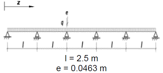
Problem formulation: a five-span beam with equal spans of 2.5 m is loaded with a transverse uniformly distributed load of 20 kN/m in the plane of the web. The cross-section of the beam is a C-shaped thin-walled cold-formed profile. The load is applied to the top flange of the beam in the plane of the web with an eccentricity relative to the center of mass of 46.3 mm. Determine the values of bimoments in the sections of the beam.
Source: A.D. Pavlenko, V.A. Rybakov, A.V. Pikht, E.S. Mikhailov. Non-uniform torsion of thin-walled open-section multi-span beams // Magazine of Civil Engineering, No. 7(67), 2016, pp. 55-69.
Initial data file:
Rybakov_5SpanBeam.spr;
SCAD version used:
SCAD++ 23.1.1.3, 18.06.2024
Initial data:
| Е = 210000 N/mm2 | elastic modulus |
| v = 0.3 | Poisson’s ratio |
| Section type | Channel |
| h = 220 mm | Section height (along the outer edge) |
| b = 70 mm | Flange width (along the outer edge) |
| t = 2 mm | Profile thickness (minus the coating thickness) |
| q = 20 kN/m | Uniformly distributed load on the beam |
| l = 2.5 m | Length of each beam span |
| е = 46.3 mm | Eccentricity of the applied load (the load is applied to the top flange of the profile, at the middle of the flange). |
Finite element model: the design model of the multi-span beam is a spatial bar system. The axis of the beam is aligned with the x – x axis of the global coordinate system. At the left end support, there are constraints on rotation about the x – x axis as well as linear displacements in the y – y and z – z directions of the global coordinate system. At the intermediate supports, there are constraints on linear displacements in the y – y and z – z directions.
Taking into account the overlap joints of the multi-span beam, the condition of equal warping was set at the intermediate supports. Additionally, this condition was set at all intermediate nodes of the beam. At the end supports of the beam, the condition of zero bimoment was achieved by introducing a hinge for warping.
The eccentricity of the application of the uniformly distributed load on the beam was taken into account by applying a uniformly distributed torque of М = q×е = 20 kN/m × 46.3 mm = 0,926 kNm/m.
Results in SCAD++:
The resulting bimoment diagram, calculated in SCAD++, is shown in Fig. 1.
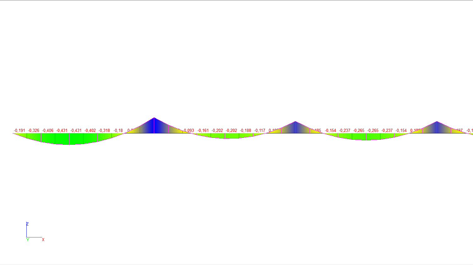
Figure 1. Bimoment diagram under constrained torsion of a five-span beam with spans of 2.5 m.
Comparison of solutions
|
Design model of the beam |
Beam section position |
|||||
|---|---|---|---|---|---|---|
|
|
z = 1 m |
z = 1,25 m |
z = 2,5 m |
z = 3,75 m |
z = 5,0 m |
z = 6,25 m |
|
Bimoment (analytical solution), kNm2 |
0,43 |
0,39 |
–0,59 |
0,19 |
–0,45 |
0,25 |
|
Bimoment in SCAD++, kNm2 |
0,4253 |
0,395 |
–0,5958 |
0,1929 |
–0,4533 |
0,2551 |
|
Deviation, % |
1,09 |
1,28 |
0,97 |
1,53 |
0,73 |
2,04 |