Stress-Strain State of a Simply Supported Beam Subjected to Longitudinal-Transverse Bending

Objective: Longitudinal-transverse bending in one plane.
Initial data files:
|
File name |
Description |
|
Longitudinal-transverse bending under a longitudinal compressive force |
|
|
Longitudinal-transverse bending under a longitudinal tensile force |
Problem formulation: A simply supported beam under pure bending is additionally loaded by a longitudinal force. Determine the maximum transverse displacements w(x) and bending moments M(x) under a longitudinal compressive and tensile force.
References: Strength Analysis in Mechanical Engineering / S. D. Ponomarev, V. L. Biderman, K. K. Likharev, et al., In three volumes. Volume 1. M.: Mashgiz, 1956.
Initial data:
| E = 1.0·1010 Pa | - elastic modulus; |
| μ = 0.3 | - Poisson’s ratio; |
| F = 1·10-2 m2 | - cross-sectional area; |
| I = 8.333·10-6 m4 | - cross-sectional moment of inertia; |
| M = 10 kN·m | - value of the bending moment; |
| N = ±200 kN | - value of the concentrated force; |
| l = 1.0 m | - beam length. |
Finite element model: The calculation is performed in the geometrically linear formulation for an energetically equivalent model in the form of a bar on the elastic subgrade resisting the rotations of its sections with a linear stiffness parameter kφ = N. Design model – plane frame, 16 bar elements of type 2, 17 elements of concentrated rotational (clock) springs with stiffness CUY = -12.5 kN·m/rad (-6.25 kN·m/rad) for a bar under compression and bending and CUY = 12.5 kN m/rad (6.25 kN·m/rad) for a bar under tension and bending of type 51, 17 nodes.
Results in SCAD
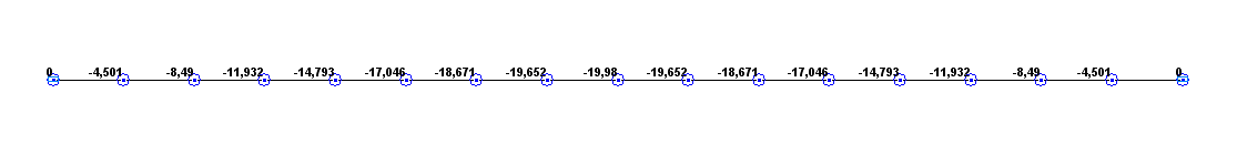
Values of transverse displacements w under a longitudinal compressive force (mm)
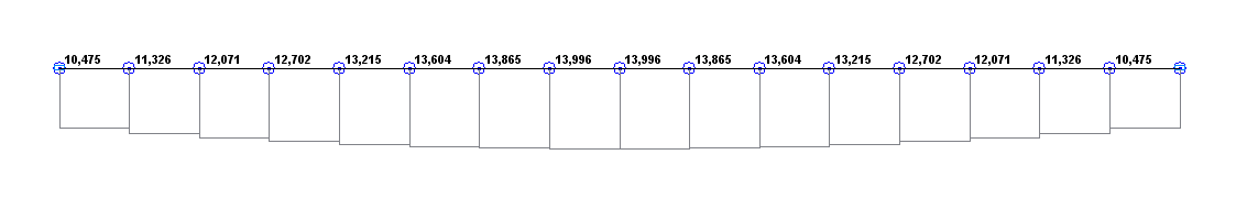
Bending moment diagram M under a longitudinal compressive force (kN·m)

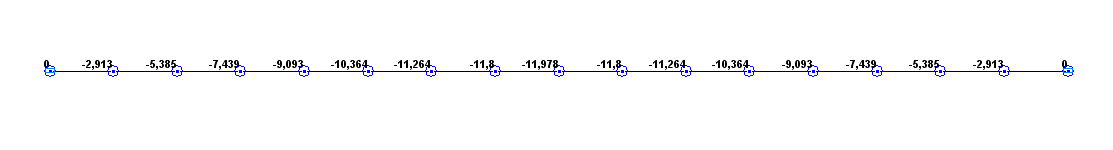
Values of transverse displacements w under a longitudinal tensile force (mm)
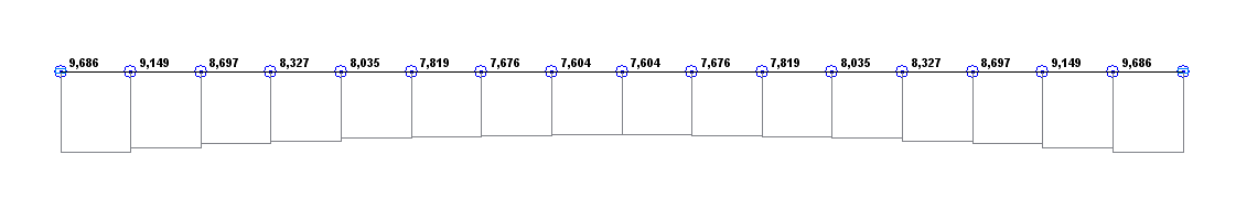
Bending moment diagram M under a longitudinal tensile force (kN·m)
Comparison of solutions:
|
Parameter |
Longitudinal compressive force |
Longitudinal tensile force |
||||
|---|---|---|---|---|---|---|
|
Theory |
SCAD |
Deviations, % |
Theory |
SCAD |
Deviations, % |
|
|
Transverse displacements w(0.5·l), mm |
-19.959 |
-19.980 |
0.11 |
-11.986 |
-11.978 |
0.07 |
|
Bending moment M(0.5·l), kN·m |
13.992 |
13.996 |
0.03 |
7.603 |
7.604 |
0.01 |
Notes: In the analytical solution, the equation of the elastic line w(x) and the equation of the bending moment M(x) under a longitudinal compressive force are determined according to the following formulas:
\[ w\left( x \right)=\frac{M}{N}\cdot \left[ {\frac{\cos \left( {k\cdot l} \right)-1}{\sin \left( {k\cdot l} \right)}\cdot \sin \left( {k\cdot x} \right)-\cos \left( {k\cdot x} \right)+1} \right]; \] \[ M\left( x \right)=M\cdot \left[ {\frac{1-\cos \left( {k\cdot l} \right)}{\sin \left( {k\cdot l} \right)}\cdot \sin \left( {k\cdot x} \right)+\cos \left( {k\cdot x} \right)} \right], \] where: \[ k=\sqrt {\frac{N}{E\cdot I}} . \]
In the analytical solution, the equation of the elastic line w(x) and the equation of the bending moment M(x) under a longitudinal tensile force are determined according to the following formulas:
\[ w\left( x \right)=\frac{M}{N}\cdot \left[ {\frac{1-ch\left( {k\cdot l} \right)}{sh\left( {k\cdot l} \right)}\cdot sh\left( {k\cdot x} \right)+ch\left( {k\cdot x} \right)-1} \right]; \] \[ M\left( x \right)=M\cdot \left[ {\frac{ch\left( {k\cdot l} \right)-1}{sh\left( {k\cdot l} \right)}\cdot sh\left( {k\cdot x} \right)+ch\left( {k\cdot x} \right)} \right], \] where: \[ k=\sqrt {\frac{N}{E\cdot I}} . \]