Plane Hinged Bar System Subjected to a Concentrated Force


Objective: Determination of the strain state of a plane hinged bar system subjected to a concentrated force.
Initial data file: SSLL11_v11.3.spr
Problem formulation: The plane hinged bar system consists of four inclined bars. The bars in the first pair have the same lengths and rigidities of the cross-section, go upward to the common node (point C) and are simply supported in the opposite nodes (points A and B). The bars in the second pair have the same rigidities of the cross-section, go upward to the common node (point D) and are attached to one of the bars of the first pair at the opposite nodes (points C and B). A vertical concentrated force F is applied in the common node of the second pair of bars. Determine horizontal X and vertical Z displacements of the common nodes of the first (point C) and second (point D) pairs of bars of the system.
References: S. S. Rao, The finite element method in engineering, 4 ed, Elsevier science end technology books, 2004, p. 313.
Initial data:
| E = 2.0·1010 Pa | - elastic modulus of the bars of the system; |
|
XA = 0.0 m |
- coordinates of the node A; |
| XB = 1.0 m YB = 0.0 m |
- coordinates of the node B; |
| XC = 0.5 m YC = 0.5 m |
- coordinates of the node C; |
| XD = 2.0 m YD = 1.0 m |
- coordinates of the node D; |
| AAC = 2.0·10-4 m2 | - cross-sectional area of the bar AC; |
| ABC = 2.0·10-4 m2 | - cross-sectional area of the bar BC; |
| ACD = 1.0·10-4 m2 | - cross-sectional area of the bar CD; |
| ABD = 1.0·10-4 m2 | - cross-sectional area of the bar BD; |
| F = 1.0·103 N | - value of the vertical concentrated force. |
Finite element model: Design model – plane hinged bar system, 4 bar elements of type 10. Boundary conditions are provided by imposing constraints in the directions of the degrees of freedom X, Z for pinned support nodes (points A and B). Number of nodes in the design model – 4.
Results in SCAD
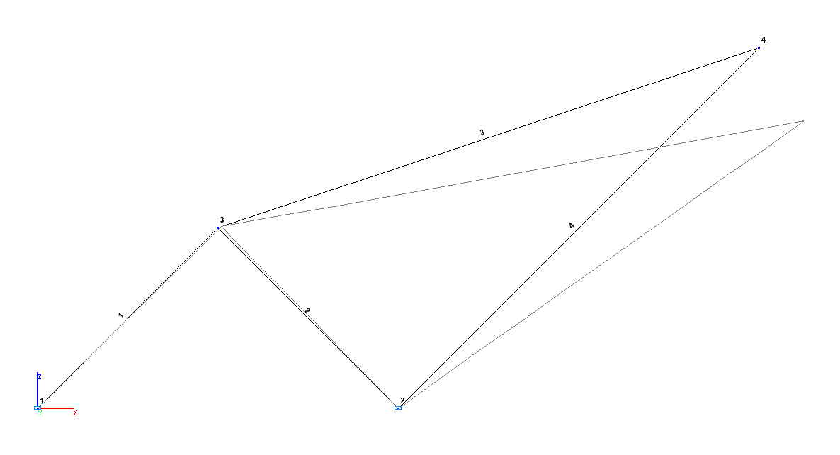
 Design and deformed models
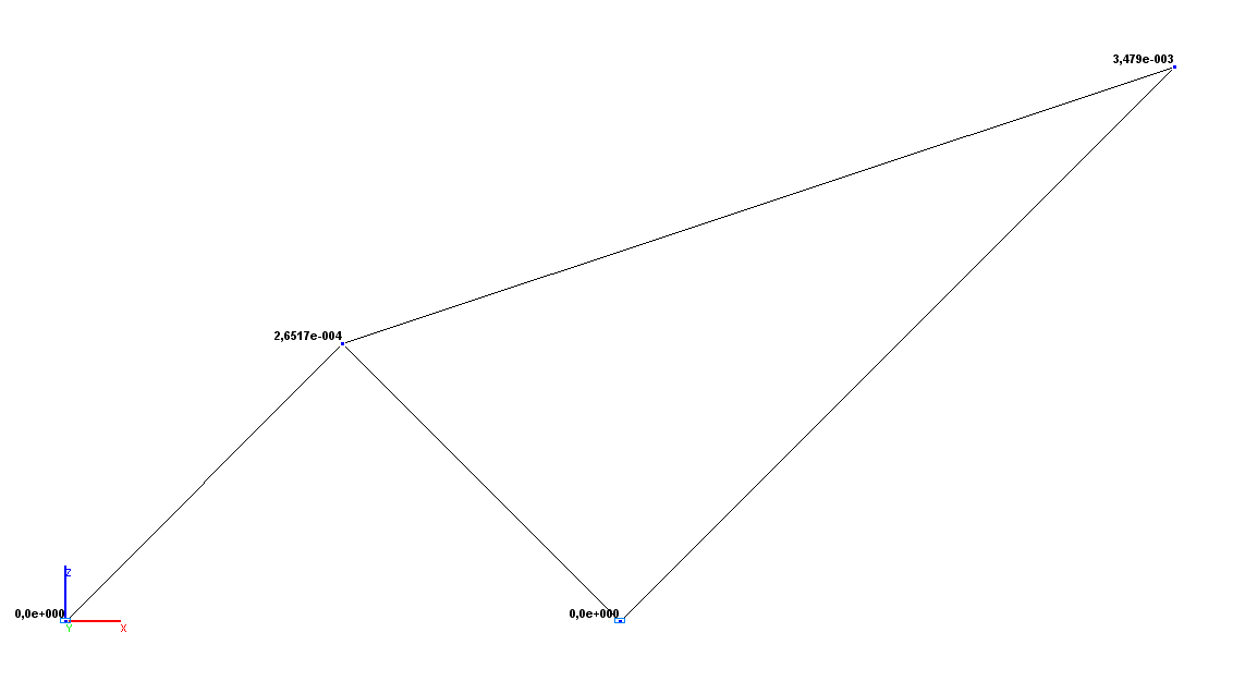 Values of horizontal displacements X (m)

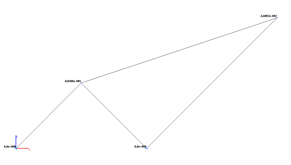
Values of vertical displacements Z (m)
Comparison of solutions:
|
Parameter |
Theory |
SCAD |
Deviations, % |
|---|---|---|---|
|
Horizontal displacement X (point C), m |
2.6517·10-4 |
2.6517·10-4 |
0.00 |
|
Vertical displacement Z (point C), m |
0.8839·10-4 |
0.8839·10-4 |
0.00 |
|
Horizontal displacement X (point D), m |
34.7903·10-4 |
34.7903·10-4 |
0.00 |
|
Vertical displacement Z (point D), m |
-56.0035·10-4 |
-56.0035·10-4 |
0.00 |