System of Cross Bars Subjected to a Distributed Load and a Concentrated Force in Their Plane

Objective: Determination of the stress-strain state of a system of cross bars subjected to a distributed load and a concentrated force in their plane.
Initial data file: SSLL10_v11.3.spr
Problem formulation: The system consists of two cross bars of square cross-section, horizontal (BD) and vertical (CE), rigidly connected in the common node (point А). The horizontal bar is clamped in the left and right nodes (points D and B). The vertical bar is clamped in the lower node (point E) and simply supported in the upper one (point C). A vertical concentrated force F is applied in the middle of the left span of the horizontal bar (point G), and a vertical uniformly distributed load p is applied to the right span of the horizontal bar (AB). Determine the rotation angle UY in the common node of cross bars (point A) and bending moments M in the bars on both sides of the node.
References: S. Timoshenko et D.H. Young, Theorie des constructions, Paris, Librairie Polytechnique Beranger, 1949, p. 412-416.
Initial data:
| E = 2.0·1011 Pa | - elastic modulus of the bars of the system; |
| LAD = 1.0 m | - length of the left span of the horizontal bar; |
| bAD = 1.0 m | - side of the cross-section of the left span of the horizontal bar; |
| LAB = 4.0 m | - length of the right span of the horizontal bar; |
| bAB = 4.0 m | - side of the cross-section of the right span of the horizontal bar; |
| LAC = 1.0 m | - length of the upper part of the vertical bar; |
| bAC = 1.0 m | - side of the cross-section of the upper part of the vertical bar; |
| LAE = 2.0 м | - length of the lower part of the vertical bar; |
| bAE = 2.0 m | - side of the cross-section of the lower part of the vertical bar; |
| F = 1.0·105 N | - value of the vertical concentrated force; |
| p = 1.0·103 N/m | - value of the vertical uniformly distributed load. |
Finite element model: Design model – plane frame, 5 bar elements of type 10. Boundary conditions are provided by imposing constraints in the directions of the degrees of freedom X, Z for the simply supported node (point C) and in the directions of the degrees of freedom X, Z, UY for the clamped nodes (points E, D, B). Number of nodes in the design model – 6.
Results in SCAD
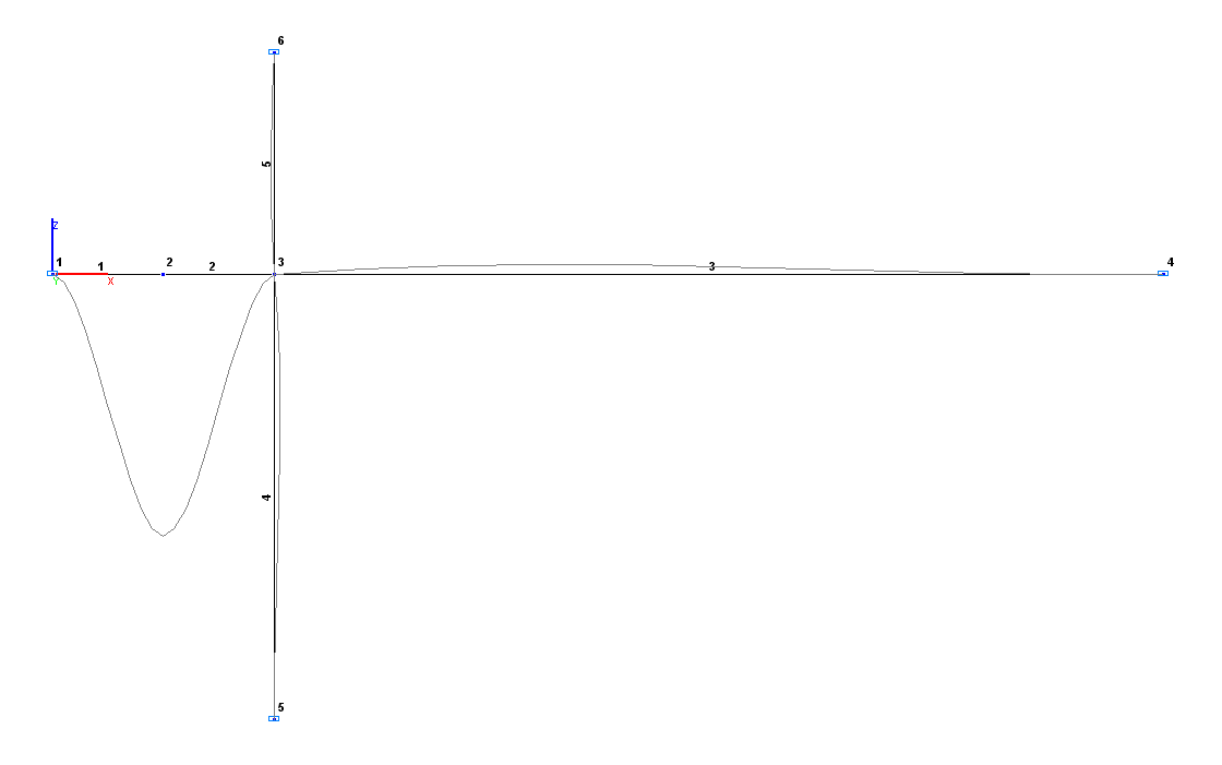
 Design and deformed models
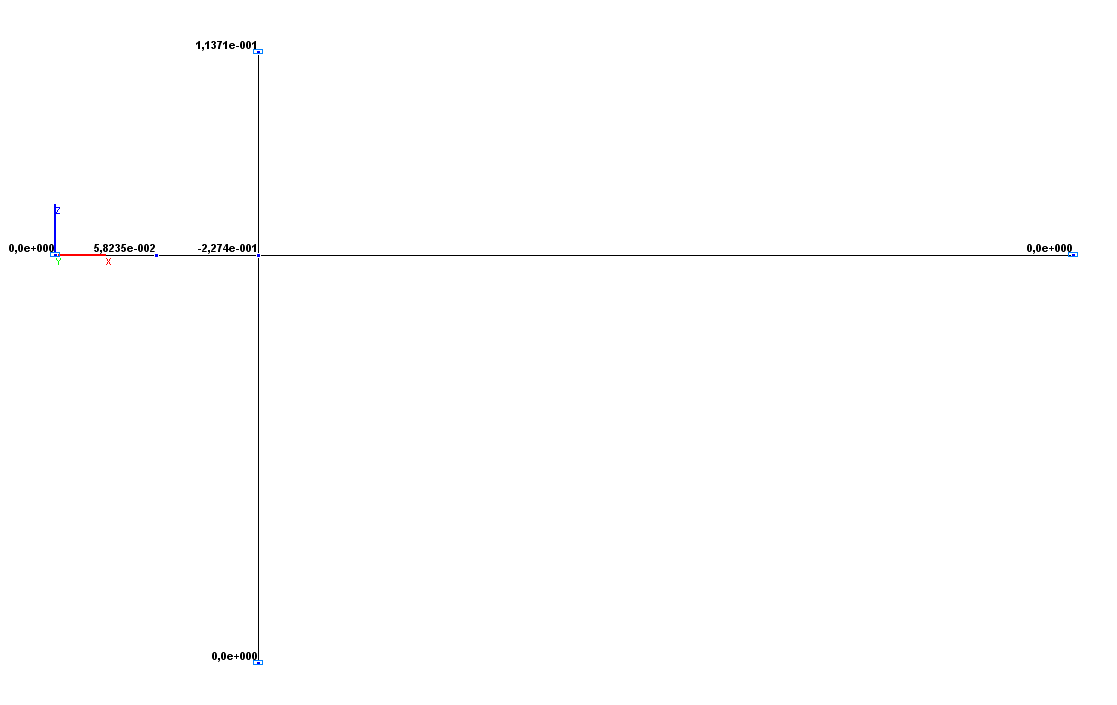
Values of rotation angles UY (rad)
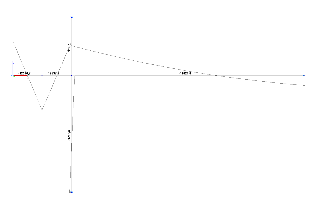
Values of bending moments M (N∙m)
Comparison of solutions:
|
Parameter |
Theory |
SCAD |
Deviations, % |
|---|---|---|---|
|
Rotation angle UY (point A), rad |
-2.2712·10-1 |
-2.2740·10-1 |
0.12 |
|
Bending moment M (bar AD), N∙m |
-12348.6 |
-12347.5 |
0.01 |
|
Bending moment M (bar AB), N∙m |
-11023.7 |
-11021.0 |
0.02 |
|
Bending moment M (bar AC), N∙m |
113.6 |
113.7 |
0.09 |
|
Bending moment M (bar AE), N∙m |
-1211.3 |
-1212.8 |
0.12 |