Cantilever Frame Subjected to a Concentrated Force

Objective: Determination of the stress-strain state of a cantilever frame subjected to a concentrated force.
Initial data file: SSLL05_v11.3.spr
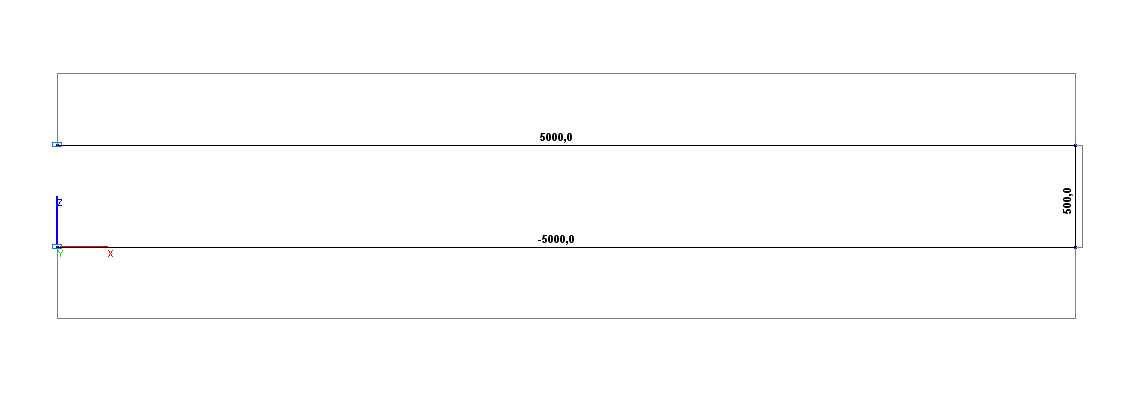
Problem formulation: The cantilever frame consists of two horizontal bars of the same length L, clamped on the left (points A, C) and joined by a vertical bar of the length l on the right (points B, D). Horizontal bars have considerable tensile/compressive stiffness, a vertical bar has both considerable tensile/compressive and bending stiffness. A vertical concentrated force F is applied in the joint between the lower horizontal bar and the vertical bar (point D). Determine the vertical displacements Z in the joints between the horizontal bars and the vertical bar (points B, D), as well as the bending moments My, shear forces Qz and longitudinal forces Nx in the clamped nodes of the horizontal bars (points A, C).
References: A. Campa, R. Chappert et R. Picand, La mecanique par les problemes, fasc. 4: Resistance des materiaux, Paris, Foucher, 1987.
Initial data:
| E = 2.0·1011 Pa | - elastic modulus of the horizontal bars; |
| L = 2.0 m | - length of the horizontal bars; |
| l = 0.2 m | - length of the vertical bar; |
| Iz = 4/3·10-8 m4 | - cross-sectional moment of inertia of the horizontal bars; |
| F = 1.0·103 N | - value of the vertical concentrated force. |
Finite element model: Design model – plane frame, 3 bar elements of type 10. Boundary conditions are provided by imposing constraints in the directions of the degrees of freedom X, Z, UY (points A, C). Tensile/compressive stiffness (E∙A) of horizontal and vertical bars is taken as 1.0·1012 N, bending stiffness of the vertical bar (E∙I) is taken as 1.0·1012 N∙m2. Number of nodes in the design model – 4.
Results in SCAD

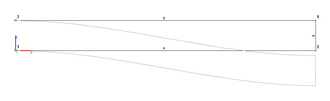
Design and deformed models
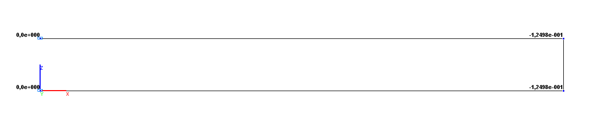
Values of vertical displacements Z (m)
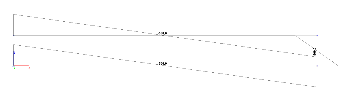
Bending moment diagram Мy (kN∙m)
Shear force diagram Qz (kN)
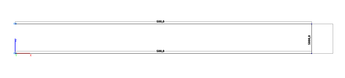
Longitudinal force diagram Nx (kN)
Comparison of solutions:
|
Parameter |
Theory |
SCAD |
Deviations, % |
|---|---|---|---|
|
Vertical displacement Z (point B), m |
-1.2500·10-1 |
-1.2498·10-1 |
0.02 |
|
Vertical displacement Z (point D), m |
-1.2500·10-1 |
-1.2498·10-1 |
0.02 |
|
Bending moment My (point A), N·m |
-500.0 |
-500.0 |
0.00 |
|
Bending moment My (point C), N·m |
-500.0 |
-500.0 |
0.00 |
|
Shear force Qz (point A), N |
500.0 |
500.0 |
0.00 |
|
Shear force Qz (point C), N |
500.0 |
500.0 |
0.00 |
|
Shear force Nx (point A), N |
5000.0 |
5000.0 |
0.00 |
|
Shear force Nx (point C), N |
-5000.0 |
-5000.0 |
0.00 |