Single-Span Simply Supported Plane Frame with a Dual-Pitched Girder Subjected to a Vertical Uniformly Distributed Load, Concentrated Vertical and Horizontal Forces and a Bending Moment

Objective: Determination of the stress-strain state of a single-span simply supported plane frame with a dual-pitched girder subjected to a vertical uniformly distributed load, concentrated vertical and horizontal forces and a bending moment.
Initial data file: SSLL14_v11.3.spr
Problem formulation: The single-span simply supported frame with a rigid connection between the dual-pitched girder and the columns is subjected to a vertical load Pzx uniformly distributed along the length of the left half-span of the girder 0.5∙L, concentrated vertical force F1 in the ridge joint (point C), concentrated horizontal force F2 and bending moment M in the joint between the girder and the left column. Determine the vertical displacement Z in the ridge joint (point C), longitudinal N and shear Q force in the support node of the left column (point A).
References: J.C. Bianchi, Rapport de la SOCOTEC, Paris, non publie, 1964.
Initial data:
| Material: | |
| E = 2.1∙1011 Pa | - elastic modulus; |
| Columns L1: | |
| h = 8.0 m | - height; |
| EA1 = 1.0∙1010 N | - axial stiffness; |
| EI1 = 2.1∙1011 ∙ 5.0∙10-4 = 10.5∙107 N∙m2 | - bending stiffness; |
| Girder L2: | |
| L = 20.0 m | - span length; |
| a = 4.0 m | - rise; |
| b = ((0.5∙20.0)2 + 4.02)0.5 | - length of the slope; |
| EA2 = 1.0∙1010 N | - axial stiffness; |
| EI2 = 2.1∙1011∙2.5∙10-4 = 5.25∙107 N∙m2 | - bending stiffness; |
| Loads and actions: | |
| Pzx = 3.0∙103 N/m | - vertical load uniformly distributed along the length of the left half-span of the girder 0.5∙L;; |
|
Pz = 3.0∙103∙0.5∙20.0/((0.5∙20.0)2 + 4.02)0.5 = 2.78543∙103 N/m |
- the same load distributed along the length of the left slope of the girder b; |
| F1 = 2.0∙104 N | - concentrated vertical force in the ridge joint; |
| F2 = 1.0∙104 N | - concentrated horizontal force in the joint between the girder and the left column; |
| M = 1.0∙105 N∙m | - concentrated bending moment in the joint between the girder and the left column. |
Finite element model: Design model – plane frame, girder – 2 elements of type 2, columns – 2 elements of type 2. Boundary conditions are provided by imposing constraints in the directions of the degrees of freedom X, Z for pinned support nodes. Number of nodes in the design model – 5.
Results in SCAD

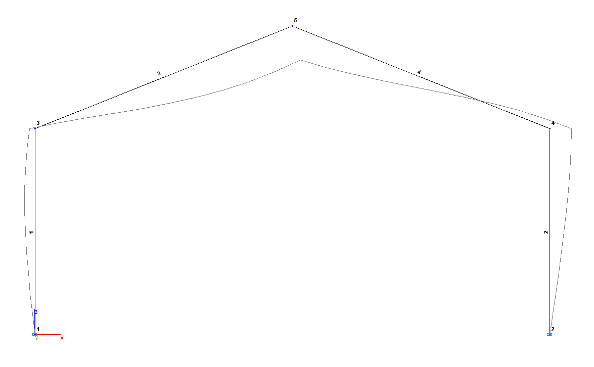
Design and deformed models
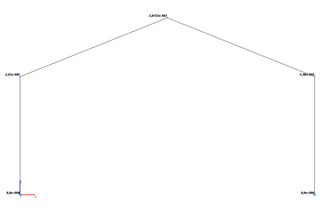
Values of vertical displacements Z (m)
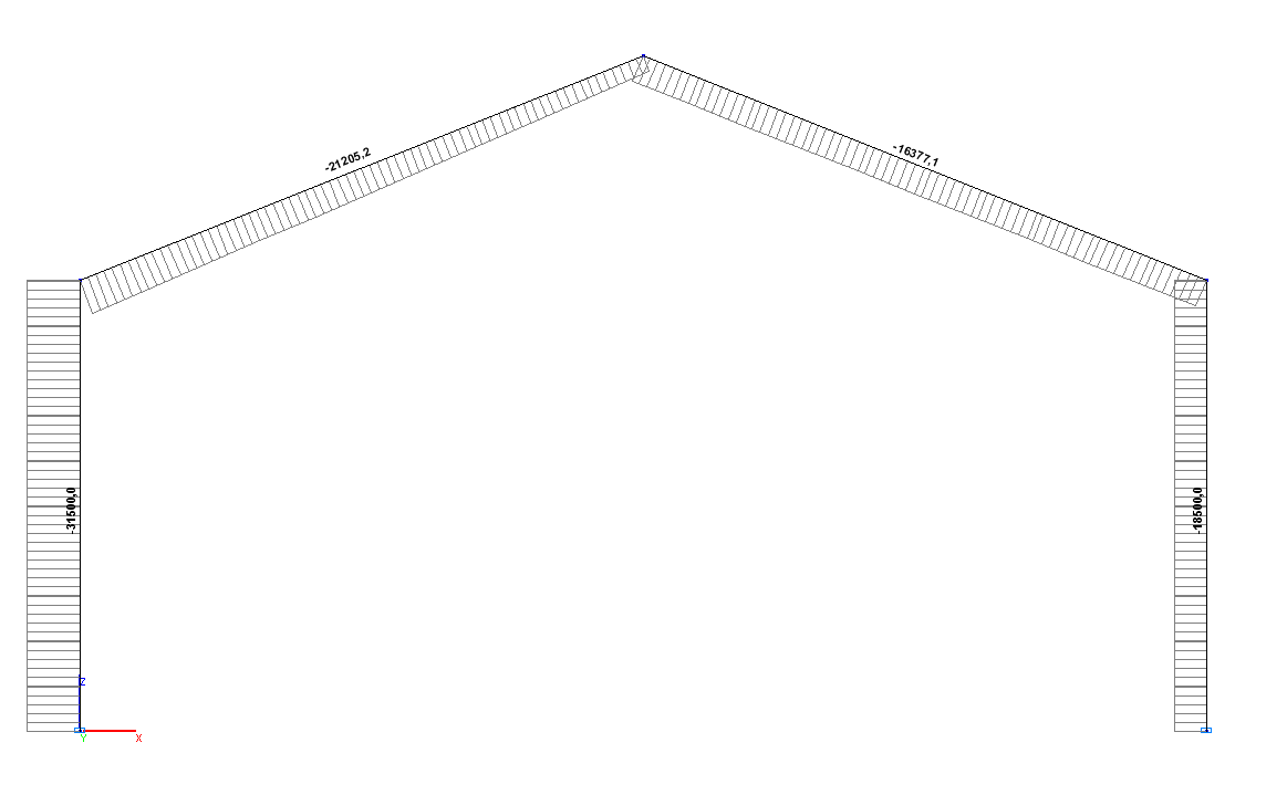
Values of longitudinal forces N (N)
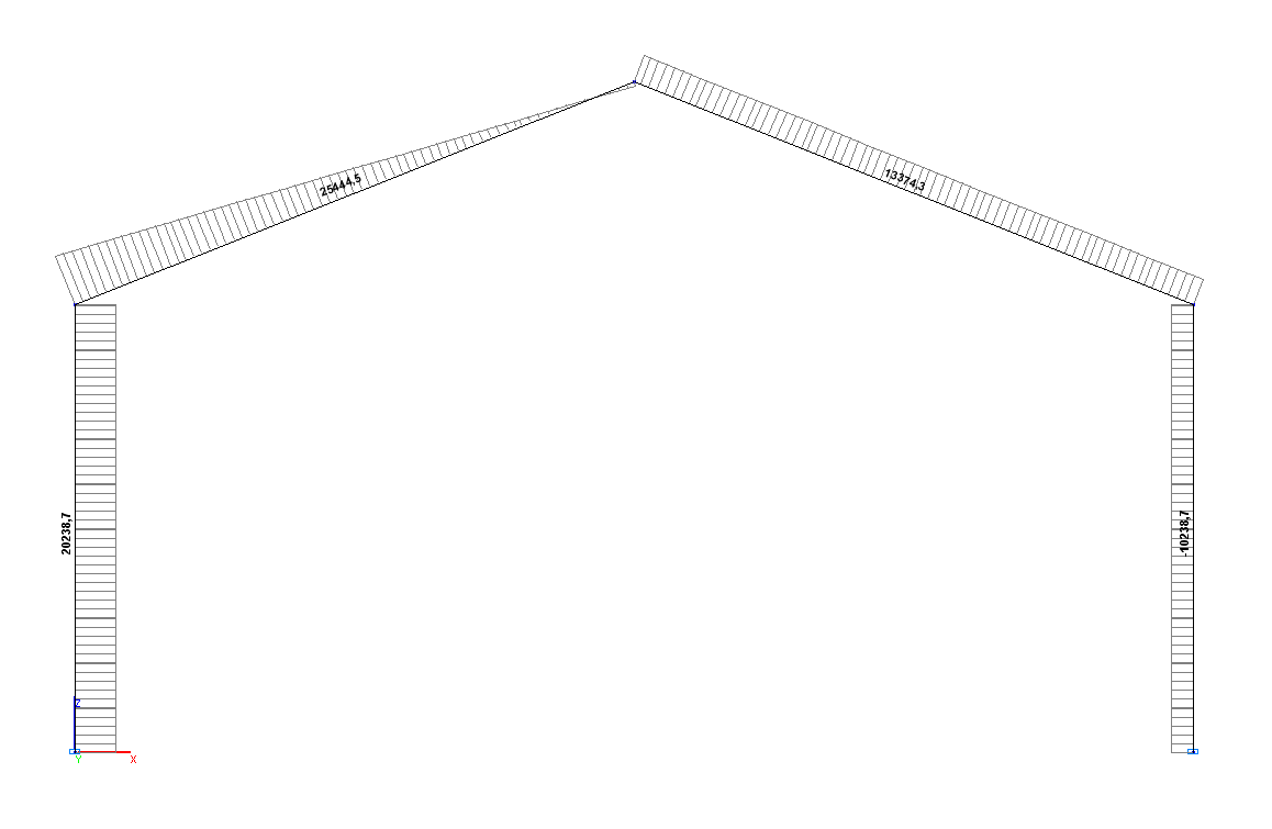
Values of shear forces Q (N)
Comparison of solutions:
|
Parameter |
Theory |
SCAD |
Deviations, % |
|
Vertical displacement ZC, m |
-3.0720∙10-2 |
-3.0752∙10-2 |
0.10 |
|
Longitudinal force NA, N |
-31.500 |
-31.500 |
0.00 |
|
Shear force NA, N |
20239.4 |
20238.7 |
0.00 |