Spatial Bar System with Elastic Constraints Subjected to a Concentrated Force

Objective: Determination of the stress-strain state of the spatial bar system with elastic constraints subjected to a concentrated force.
Initial data file: SSLL04_v11.3.spr
Problem formulation: The spatial system consists of four bars connected in series. End bars lie orthogonally in parallel horizontal planes, intermediate bars are vertical and are connected by hinges relatively to the angular degrees of freedom (point 3). There are rigid constraints of linear and angular degrees of freedom in the plane of the cross-section of the respective end bar and elastic constraints of linear and angular degrees of freedom out of the plane of the cross-section of the respective end bar on both ends of the spatial system (points 1,5). A vertical concentrated force F is applied in the joint between the upper horizontal and vertical bars (point 4). Determine the vertical displacement Z for the joint between vertical bars (point 3), horizontal displacement Y along the upper end bar and the rotation angle UX in the vertical plane containing this bar for the upper constraint of the spatial system (point 5), as well as the torque and bending moments Mx, My, Mz for the upper and lower constraints of the spatial system (points 1, 5).
References: M. Laredo, Resistance des materiaux, Paris, Dunod, 1970, p. 165.
Initial data:
| E = 2.1·1011 Pa | - elastic modulus, |
| G = 0.7875·1011 Pa | - shear modulus, |
| l = 2.0 m | - length of the horizontal bars; |
| 0.5 l = 1.0 m | - length of the vertical bars; |
| A = 1.0·10-3 m2 | - cross-sectional area of the bars; |
| Ix = 2·10-6 m4 | - moment of inertia in the plane of the cross-section of the bars (torsion); |
| Iy = Iz = 2·10-6 m4 | - moments of inertia out of the plane of the cross-section of the bars (bending); |
| k = 5.25·104 N/m | - stiffness of constraints with respect to the linear degree of freedom; |
| ku = 5.25·104 N∙m/rad | - stiffness of constraints with respect to the angular degrees of freedom; |
| F = 1.0·104 N | - value of the vertical concentrated force. |
Finite element model: Design model – general type system, 4 bar elements of type10. Boundary conditions are provided by imposing rigid constraints in the directions of the degrees of freedom X, Z, UY and constraints of finite rigidity in the directions of the degrees of freedom Y, UX, UZ (member type 51) – for the end of the upper bar of the spatial system (point 5); by imposing rigid constraints in the directions of the degrees of freedom Y, Z, UX and constraints of finite rigidity in the directions of the degrees of freedom X, UY, UZ (member type 51) – for the end of the lower bar of the spatial system (point 1). Number of nodes in the design model – 5.
Results in SCAD

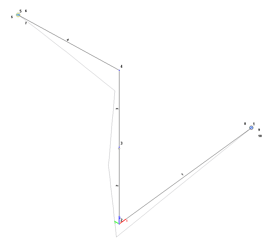
Design and deformed models

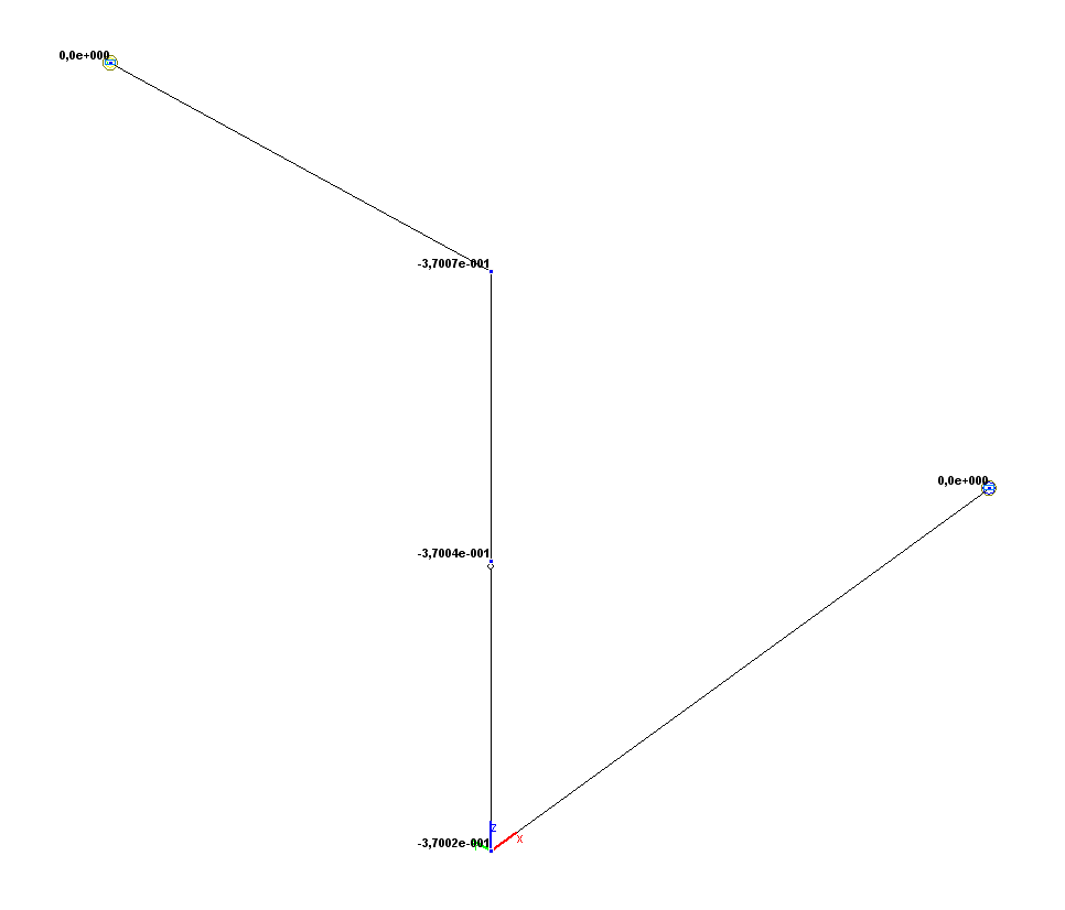
Values of vertical displacements Z (m)

Values of horizontal displacements Y (m)
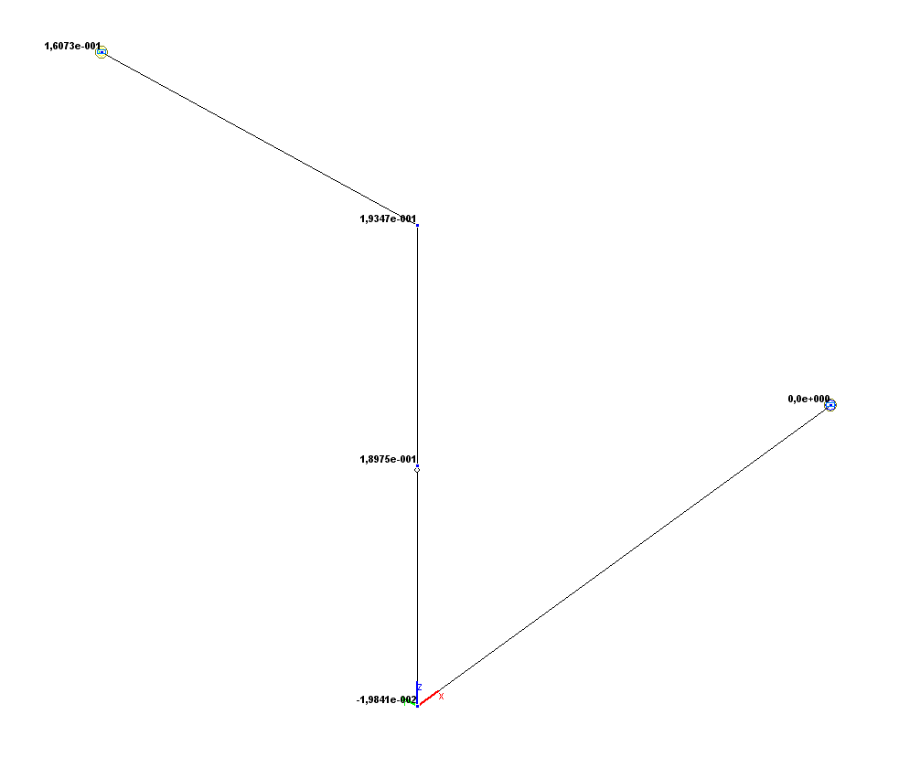
Values of rotation angles UX (rad)
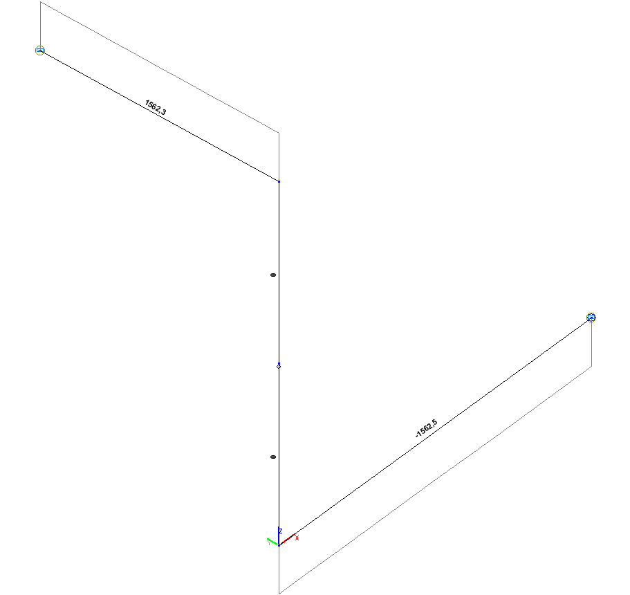
Torque diagram Мx (kN*m)
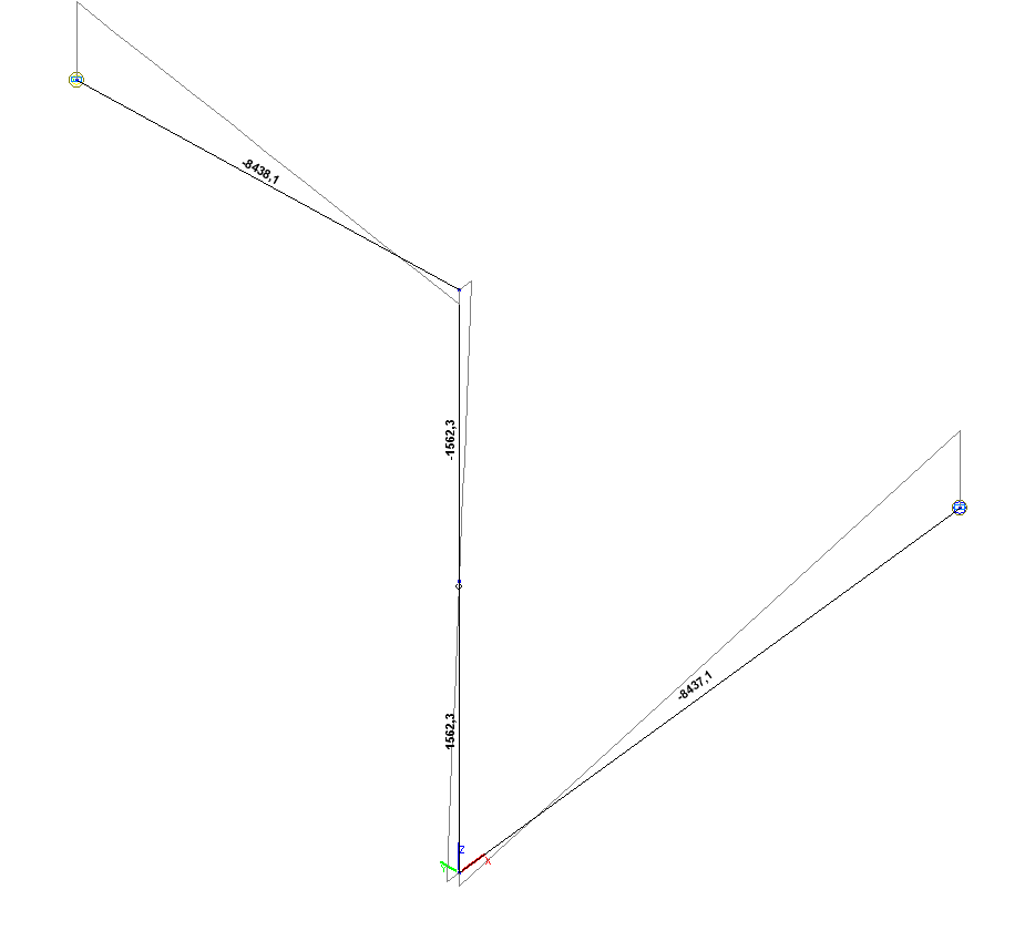
Bending moment diagram Мy (kN*m)

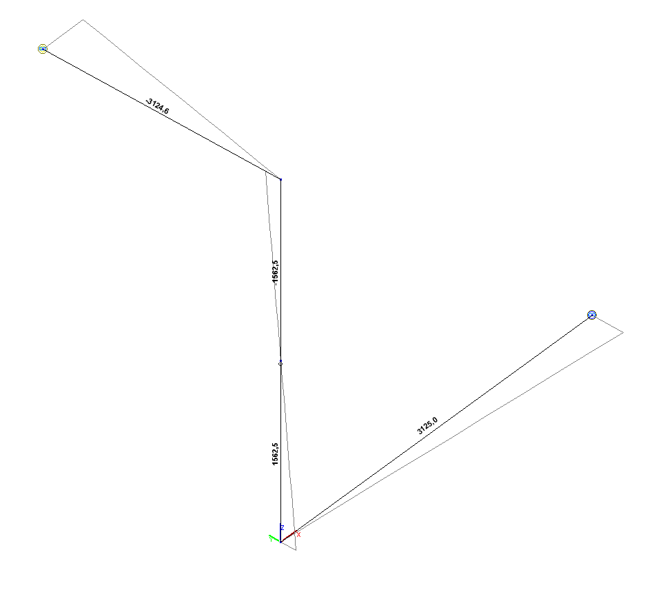
Bending moment diagram Мz (kN*m)
Comparison of solutions:
|
Parameter |
Theory |
SCAD |
Deviations, % |
|---|---|---|---|
|
Vertical displacement Z (point 3), m |
-3.7004·10-1 |
-3.7004·10-1 |
0.00 |
|
Horizontal displacement Y (point 5), m |
-2.9762·10-2 |
-2.9762·10-2 |
0.00 |
|
Rotation angle UX (point 5), rad |
1.6071·10-1 |
1.6073·10-1 |
0.01 |
|
Torque Mx (point 5), N·m |
1562.5 |
1562.3 |
0.01 |
|
Bending moment My (point 5), N·m |
-8437.5 |
-8438.1 |
0.01 |
|
Bending moment Mz (point 5), N·m |
-3125.0 |
3124.6 |
0.01 |
|
Torque Mx (point 1), N·m |
-1562.5 |
-1562.5 |
0.00 |
|
Bending moment My (point 1), N·m |
-8437.5 |
-8437.1 |
0.00 |
|
Bending moment Mz (point 1), N·m |
3125.0 |
3125.0 |
0.00 |