Simply Supported Semicircular Arch of Constant Cross-Section Subjected to a Concentrated Force Acting in Its Plane

Objective: Determination of the strain state of a simply supported semicircular arch of constant cross-section subjected to a concentrated force acting in its plane.
Initial data file: SSLL08_v11.3.spr
Problem formulation: The semicircular arch of constant cross-section with pinned and roller supports subjected to a concentrated force F acting in its plane at the level of the key, directed downward along the normal to the longitudinal axis. Determine the deflection of the longitudinal axis of the arch Z, displacement of the roller support X and rotation angles of the support hinges UY.
References: P. Dellus, Resistance de materiaux, Paris, Technique et Vulgarisation, 1958.
Initial data:
| E = 2.0·1011 Pa | - elastic modulus of a semicircular arch; |
| r = 1.0 m | - arc radius of the longitudinal axis of the semicircular arch; |
| de = 0.020 m | - outer diameter of the ring cross-section of the arch; |
| di = 0.016 m | - inner diameter of the ring cross-section of the arch; |
| F = 100 N | - value of the concentrated force. |
Finite element model: Design model – plane frame, 48 bar elements of type 10. Boundary conditions are provided by imposing constraints in the directions of the degrees of freedom X, Z – for the pinned support and Z – for the roller support. Number of nodes in the design model – 49.
Results in SCAD

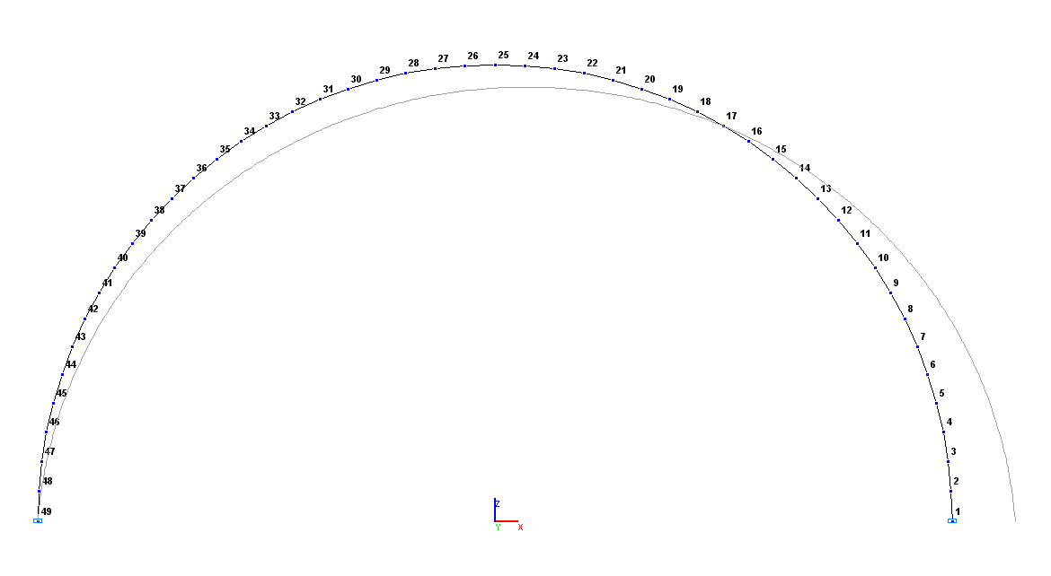
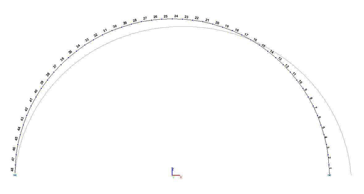
Design and deformed models
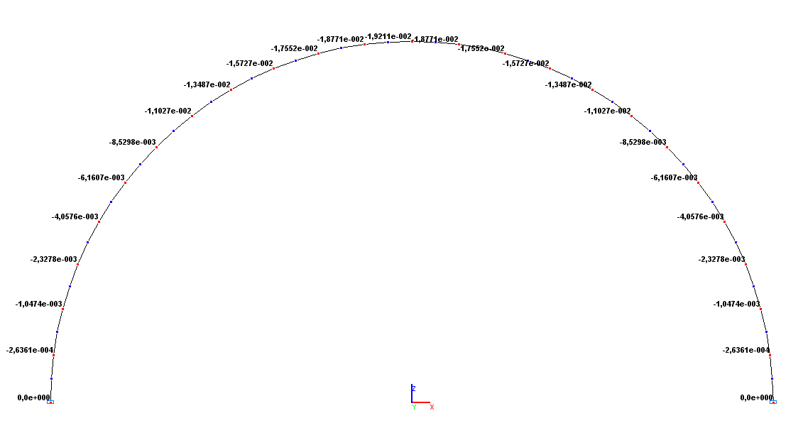
Values of vertical displacements Z (m)
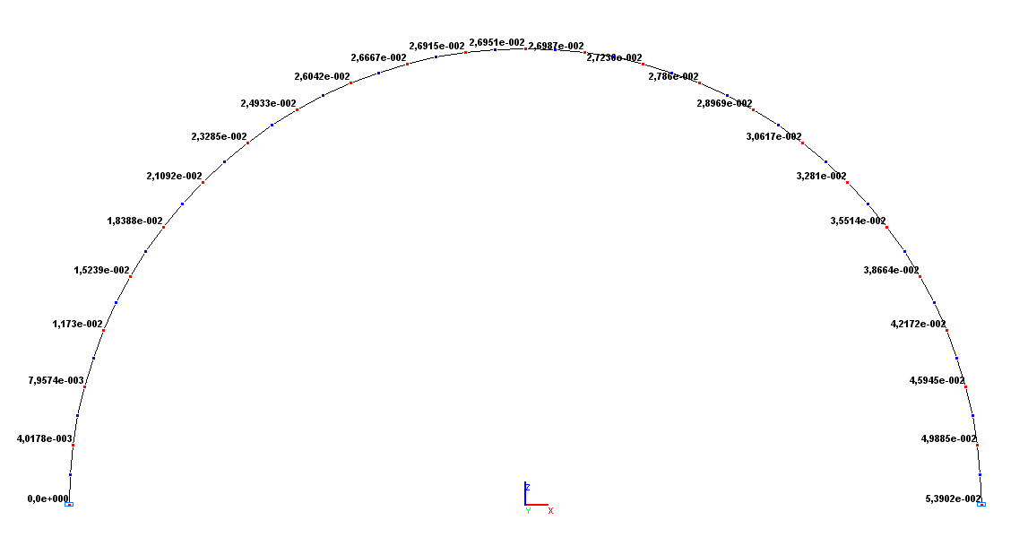
Values of horizontal displacements X (m)
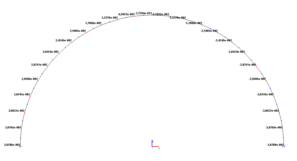
Values of rotation angles UY (rad)
Comparison of solutions:
|
Parameter |
Theory |
SCAD |
Deviations, % |
|---|---|---|---|
|
Deflection of the longitudinal axis of the arch Z, m |
-1.9206·10-2 |
-1.9211·10-2 |
0.03 |
|
Displacement of the roller support X, m |
5.3912·10-2 |
5.3902·10-2 |
0.02 |
|
Rotation angle of the roller support UY, rad |
-3.0774·10-2 |
-3.0788·10-2 |
0.05 |
|
Rotation angle of the pinned support UY, rad |
3.0774·10-2 |
3.0788·10-2 |
0.05 |
Notes: In the analytical solution, the deflection of the longitudinal axis of the arch Z, the displacement of the roller support X and the rotation angles of the support hinges UY are determined according to the following formulas:
\[Z=\frac{\pi }{8}\cdot \frac{F\cdot r}{E\cdot A}+\left( {\frac{3\cdot \pi }{8}-1} \right)\cdot \frac{F\cdot r^{3}}{E\cdot I}; \quad X=\frac{1}{2}\cdot \frac{F\cdot r}{E\cdot A}-\frac{1}{2}\cdot \frac{F\cdot r^{3}}{E\cdot I}; \quad UY=\pm \left( {\frac{\pi }{4}-\frac{1}{2}} \right)\frac{F\cdot r^{2}}{E\cdot I}, where: \] \[ I=\frac{\pi \cdot d_{e}^{2}}{4}\cdot \left( {1-\left( {\frac{d_{i} }{d_{e} }} \right)^{2}} \right); \quad I=\frac{\pi \cdot d_{e}^{4}}{64}\cdot \left( {1-\left( {\frac{d_{i} }{d_{e} }} \right)^{4}} \right). \]