Cantilever Curved Beam with a Transverse Concentrated Force at Its Free End
Objective: Check of the accuracy of the determination of the displacement value for the free end of a beam in the direction of the concentrated force for models of different dimensions.
Initial data files:
| File name | Description |
|---|---|
| 4.38_c.spr | Bar model |
| 4.38_p.spr | Shell element model |
| 4.38_о.spr | Solid element model |
Problem formulation: The cantilever curved beam with a longitudinal circular axis having a length of the split ring and with a rectangular cross-section constant along the axis is subjected to a transverse concentrated force P applied at its free end. Determine the displacement of the free end of the beam w in the direction of the concentrated force.
References: Sacharov A., Altenbach J.: Finite Elements in Solid Mechanics. -Kiev: High School. 1982, Leipzig: Fahbuhferlag. 1982;
G.S. Pisarenko, A.P. Yakovlev, V.V. Matveev, Handbook on Strength of Materials. — Kiev: Naukova Dumka, 1975.
Initial data:
| E = 100.0 kPa | - elastic modulus; |
| ν = 0.0 | - Poisson’s ratio; |
| R = 0.20 m | - arc radius of the longitudinal axis of the cantilever curved beam; |
| α = 360º | - central angle of the arc length of the longitudinal axis of the cantilever curved beam; |
| b = h = 0.01 m | - cross-sectional dimensions of the cantilever curved beam; |
| P = 10-8 kN | - value of the transverse concentrated force on the free end of the beam. |
Finite element model: Design model – general type system. Three design models are considered:
Bar model (B), 120 elements of type 5, the spacing of the finite element mesh along the longitudinal axis is 3.0º, 121 nodes;
Shell element model (P), 480 eight-node elements of type 50, the spacing of the finite element mesh along the longitudinal axis is 3.0º, and along the height of the beam is 0.0025 m, 1689 nodes;
Solid element model (S), 1920 twelve-node elements of type 37, the spacing of the finite element mesh along the longitudinal axis is 3.0º, and along the height and width of the beam is 0.0025 m, 10865 nodes.
Results in SCAD

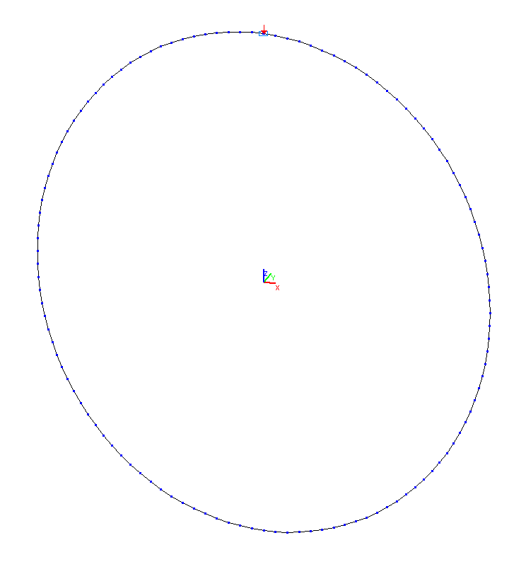
Design model. Bar model
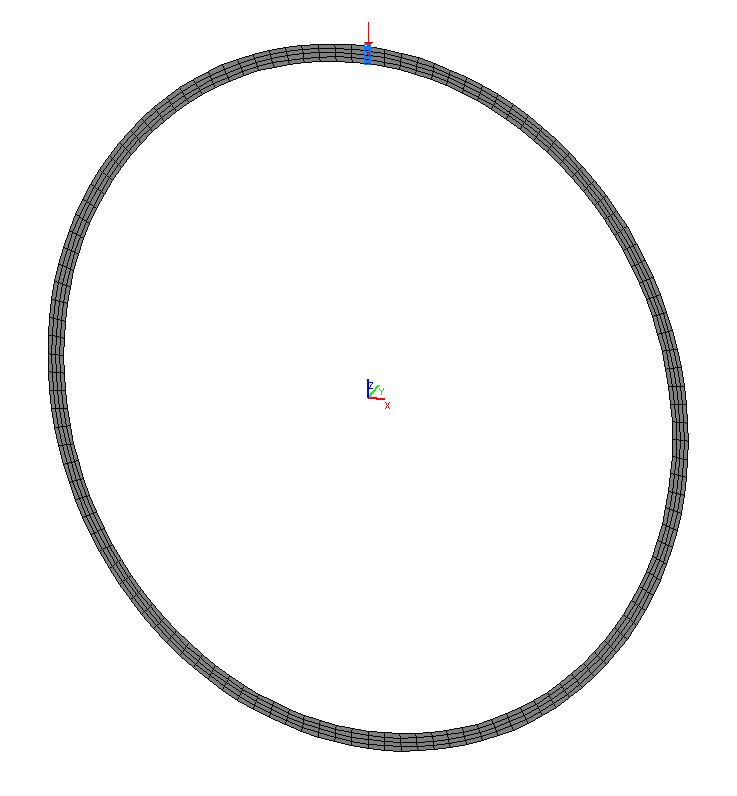
Design model. Shell element model
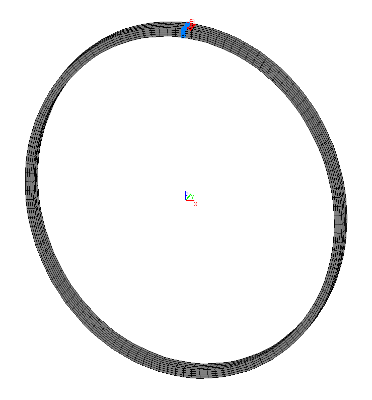
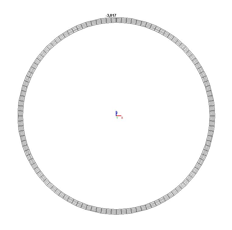
Design model. Solid element model
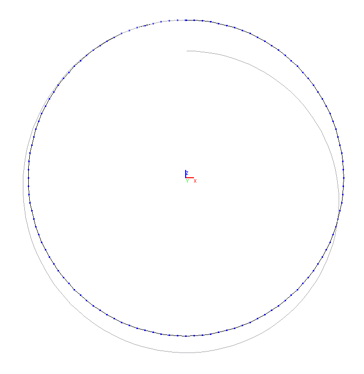
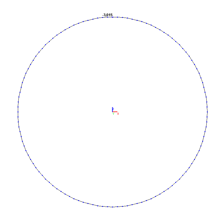
Deformed model and the values of the displacements of the free end of the beam w in the bar model (mm)
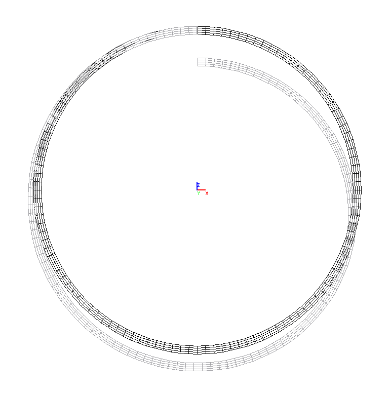
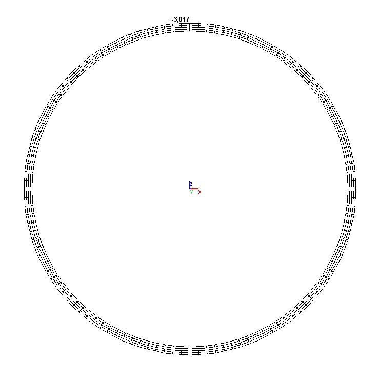
Deformed model and the values of the displacements of the free end of the beam w in the shell element model (mm)
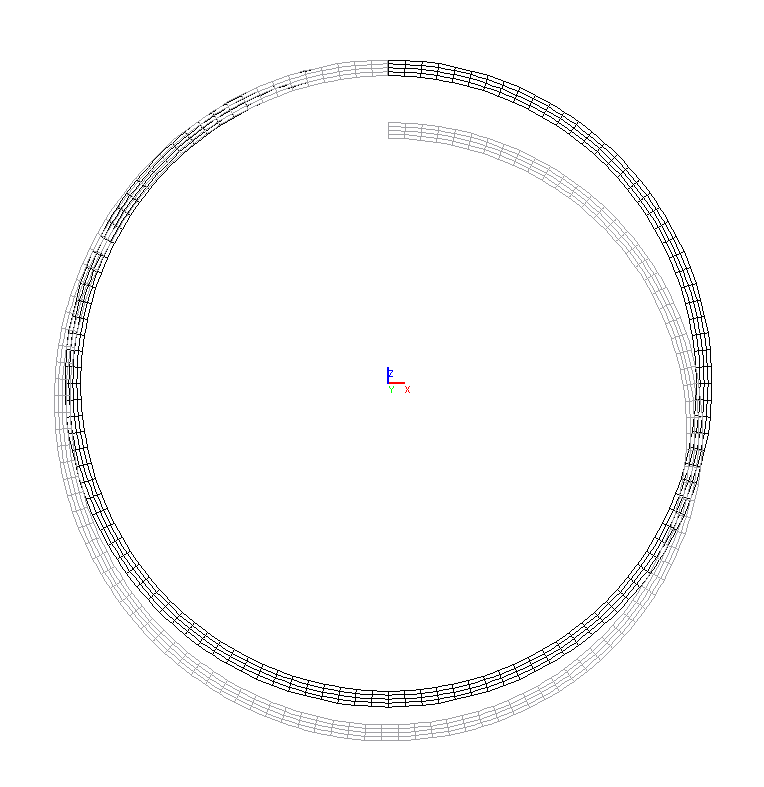
Deformed model and the values of the displacements of the free end of the beam w in the solid element model (mm)
Comparison of solutions:
|
Model |
Displacements w, mm |
Deviations, % |
|---|---|---|
|
Bar (B) |
3.015 |
0.03 |
|
Shell element (P) |
3.017 |
0.03 |
|
Solid element (S) |
3.017 |
0.03 |
|
Theory |
3.016 |
─ |
Notes: In the analytical solution the displacement of the free end of the beam w in the direction of the transverse concentrated force is determined according to the following formula (G.S. Pisarenko, A.P. Yakovlev, V.V. Matveev, Handbook on Strength of Materials. — Kiev: Naukova Dumka, 1975, p. 392):
\[ w=\frac{12\cdot P\cdot R^{3}}{E\cdot b\cdot h^{3}}\cdot \left( {\frac{\alpha }{2}-\frac{\sin \left( {2\cdot \alpha } \right)}{4}} \right). \]