Cantilever Circular Bar of Constant Cross-Section with Concentrated Forces and a Moment Acting in Its Plane at Its Free End

Objective: Determination of the strain state of a cantilever circular bar of constant cross-section with concentrated forces and a moment acting in its plane at its free end.
Initial data file:
|
File name |
Description |
|---|---|
|
Design model – plane frame. Cantilever circular bar lies in the XOZ plane of the global coordinate system |
Problem formulation: The cantilever circular bar of constant cross-section is subjected to concentrated horizontal (normal) F1 and vertical (tangential) F2 forces and a moment M acting in its plane and applied at its free end. Determine the horizontal X and vertical Z displacements , as well as the rotation angle UY of the free end of the bar (point B).
References: J.S. Przemieniecki, Theory of matrix structural analysis, New York, McGraw-Hill, 1968.
Initial data:
| E = 2.0·1011 Pa | - elastic modulus of the cantilever circular bar; |
| r = 3.0 m | - arc radius of the longitudinal axis of the cantilever circular bar; |
| α = 90º | - central angle of the arc length of the longitudinal axis of the cantilever circular bar; |
| de = 0.020 m | - outer diameter of the ring cross-section of the bar; |
| di = 0.016 m | - inner diameter of the ring cross-section of the bar; |
| F1 = 10 N | - value of the horizontal concentrated force; |
| F2 = 5 N | - value of the vertical concentrated force; |
| M = 8 N∙m | - value of the concentrated moment. |
Finite element model: Design model – plane frame, 24 bar elements of type 10. Boundary conditions are provided by imposing constraints in the directions of the degrees of freedom X, Z, UY (point A). Number of nodes in the design model – 25.
Results in SCAD

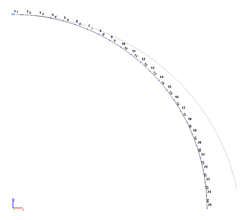
Design and deformed models
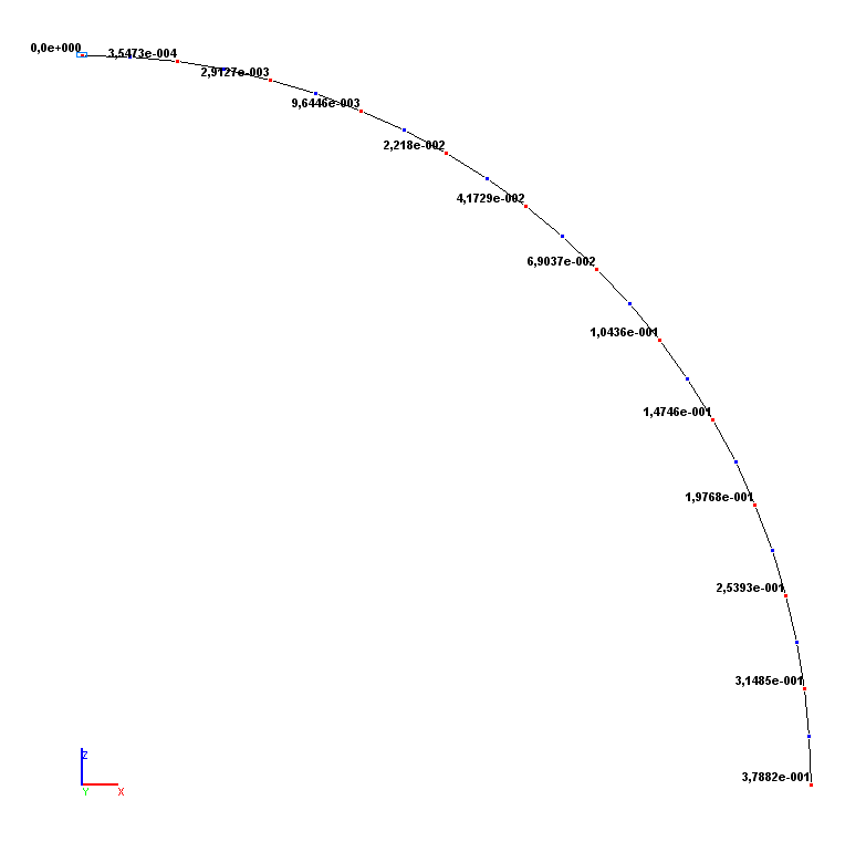
Values of horizontal displacements X (m)
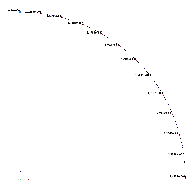
Values of vertical displacements Z (m)
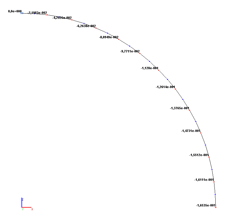
Values of rotation angles UY (rad)
Comparison of solutions:
|
Parameter |
Theory |
SCAD |
Deviations, % |
|---|---|---|---|
|
Horizontal displacement X (point B), m |
3.7908·10-1 |
3.7882·10-1 |
0.07 |
|
Vertical displacement Z (point B), m |
2.4173·10-1 |
2.4174·10-1 |
0.01 |
|
Rotation angle UY (point B), rad |
-1.6539·10-1 |
-1.6535·10-1 |
0.02 |
Notes: In the analytical solution the horizontal X and vertical Z displacements, as well as the rotation angle UY of the free end of the bar are determined according to the following formulas:
\[ X=\frac{r^{2}}{E\cdot I}\cdot \left( {M+F1\cdot r\cdot \frac{\pi }{4}+F2\cdot r\cdot \frac{1}{2}} \right); \] \[ Z=\frac{r^{2}}{E\cdot I}\cdot \left( {M\cdot \left( {\frac{\pi }{2}-1} \right)+F1\cdot r\cdot \frac{1}{2}+F2\cdot r\cdot \left( {\frac{3\cdot \pi }{4}-2} \right)} \right); \] \[ UY=-\frac{r}{E\cdot I}\cdot \left( {M\cdot \frac{\pi }{2}+F1\cdot r+F2\cdot r\cdot \left( {\frac{\pi }{2}-1} \right)} \right), where: \] \[ I=\frac{\pi \cdot d_{e}^{4}}{64}\cdot \left( {1-\left( {\frac{d_{i} }{d_{e} }} \right)^{4}} \right). \]