Cantilever Circular Bar of Constant Cross-Section with a Concentrated Force out of Its Plane at Its Free End

Objective: Determination of the stress-strain state of a cantilever circular bar of constant cross-section with a concentrated force acting out of its plane at its free end.
Initial data file:
|
File name |
Description |
|---|---|
|
Design model – general type system. Cantilever circular bar lies in the XOZ plane of the global coordinate system |
Problem formulation: The cantilever circular bar of constant cross-section is subjected to a concentrated force F acting in its plane and applied at its free end. Determine the displacement Y of the free end of the bar out of its plane (point B), as well as the torque Mx and out-of-plane bending moment Mz for the cross-section corresponding to the central angle θ from the clamped end.
References: S. Timoshenko, Strength of materials, Part 1: Elementary theory and problem, 3ed, 1955; R.J. Roark, Formulas for stress and strain, 4ed, New York, McGraw-Hill, 1965.
Initial data:
| E = 2.0·1011 Pa | - elastic modulus of the cantilever circular bar; |
| ν = 0.3 | - Poisson’s ratio; |
| r = 1.0 m | - arc radius of the longitudinal axis of the cantilever circular bar; |
| θ = 90º | - central angle of the arc length of the longitudinal axis of the cantilever circular bar; |
| de = 0.020 m | - outer diameter of the ring cross-section of the bar; |
| di = 0.016 m | - inner diameter of the ring cross-section of the bar; |
| F = 100 N | - value of the concentrated force. |
Finite element model: Design model – general type system, 15 bar elements of type 10. Boundary conditions are provided by imposing constraints in the directions of the degrees of freedom X, Y, Z, UX, UY, UZ (point A). Number of nodes in the design model – 16.
Results in SCAD

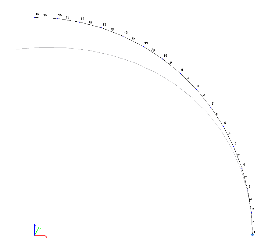
Design and deformed models
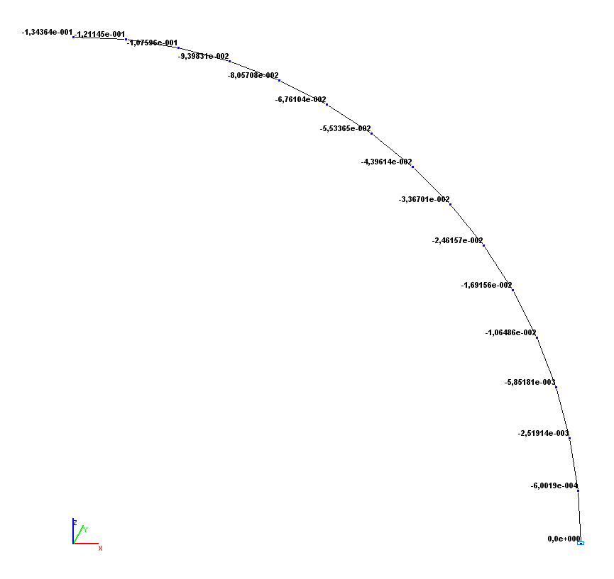
Values of displacements out of the plane of the bar Y (m)
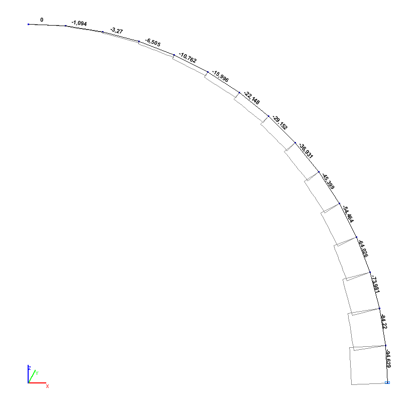
Torque diagram Мx (kN∙m)
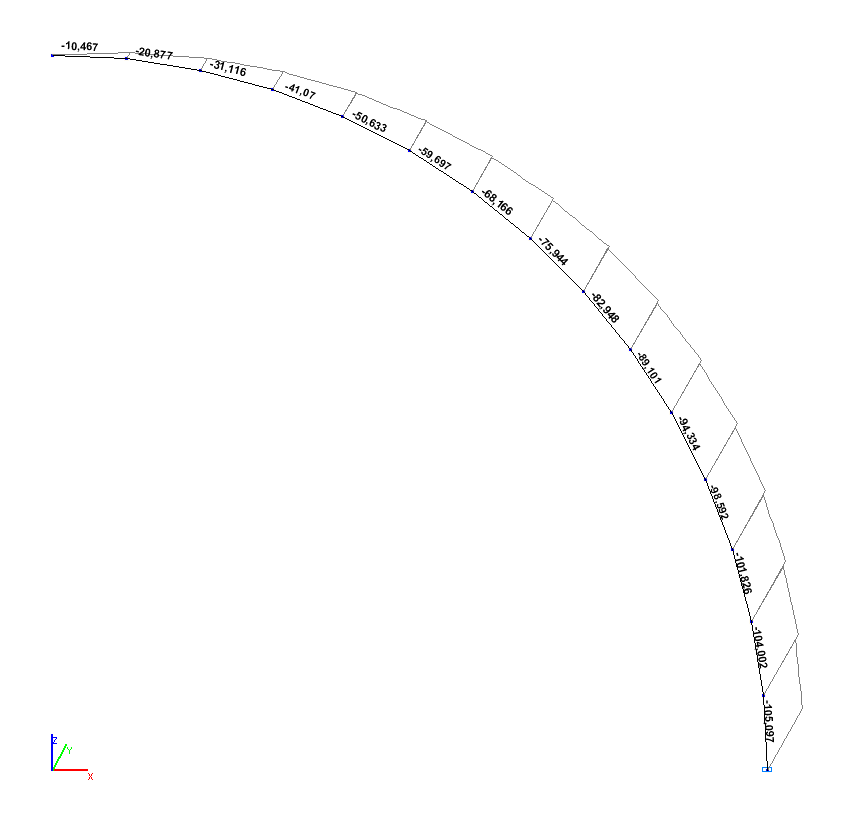
Bending moment diagram out of the plane of the bar Мz (kN∙m)
Comparison of solutions:
|
Parameter |
Theory |
SCAD |
Deviations, % |
|---|---|---|---|
|
Displacement out of the plane of the bar Y (point B), m |
-1.34462·10-1 |
-1.34364·10-1 |
0.07 |
|
Torque Mx (θ = 15º), N∙m |
-74.118 |
-73.981 |
0.18 |
|
Bending moment out of the plane of the bar Mz (θ = 15º), N∙m |
-96.593 |
-96.593 |
0.00 |
Notes: In the analytical solution the displacement Y of the free end of the bar out of its plane (point B), as well as the torque Mx and out-of-plane bending moment Mz for the cross-section corresponding to the central angle θ from the clamped end are determined according to the following formulas:
\[Y=\frac{F\cdot r^{3}}{E\cdot I}\cdot \left( {\frac{1+3\cdot \lambda }{2}\cdot \frac{\pi }{2}-2\cdot \lambda } \right), where: \] \[ I_{z} =\frac{\pi \cdot d_{e}^{4}}{64}\cdot \left( {1-\left( {\frac{d_{i} }{d_{e} }} \right)^{4}} \right), \quad \lambda =\frac{E\cdot I_{z} }{G\cdot I_{x} }=1+\nu \] (for the ring cross-section); \[ M_{x} =F\cdot r\cdot \cos \left( \theta \right); \] \[ M_{z} =F\cdot r\cdot \left( {1-\sin \left( \theta \right)} \right). \]
 .
.