Single-Span Beam with a Prestressed Tie Subjected to a Uniformly Distributed Load


Objective: Determination of the stress-strain state of a beam with a tie taking into account the transverse shear deformations in the beam.
Initial data file: SSLL13_v11.3.spr
Problem formulation: The single-span beam with a tie tightened by the displacement value δ by the struts is subjected to a uniformly distributed load q. Determine the longitudinal force N in the tie CE, the bending moment M in the section of the stiffening beam H in the middle of its span, the vertical displacement z in the joint between the strut and the stiffening beam (point D).
References: M. Laredo, Resistence des materiaux, Paris, Dunod, 1970, p. 77.
Initial data:
| Tie A1: | |
| EF = 9.450∙108 N | - axial stiffness; |
| Strut A2: | |
| EF = 7.308∙108 N | - axial stiffness; |
| Stiffening beam AB: | |
| EF = 3.1836∙109 N | - axial stiffness; |
| EIy = 4.5654∙107 N/m2 | - bending stiffness; |
| GFy = 5.09376∙108 N | - shear stiffness; |
| Loads and actions: | |
| δ = 6.52·10-3 m | - displacement in the tie; |
| P = 5.0∙104 N/m | - transverse uniformly distributed load on the stiffening beam. |
Finite element model: Design model – plane frame, tie A1 – 4 elements of type 1, struts A2 – 2 elements of type 1, stiffening beam AB – 3 elements of type 2 taking into account the shear, elements modeling the prestressing of the tie in the CE section – 2 elements of type 154 with the axial stiffness EF = 1.0∙1018 N. The tie in the CE section is represented by two elements of equal length increased with respect to half the length of the section by imposing rigid inserts in the longitudinal direction. The length of the elements is increased in order to separate their nodes near the symmetry axis of the structure at the prestressing stage. A null element is attached to each of these nodes, with the help of which they are displaced in the longitudinal direction. In order to prevent the dimensional instability of the system the displacements of nodes are combined by elements in the transverse direction by the degree of freedom Z in the section of the tie CE. Boundary conditions in the direction of the degree of freedom Z in the support nodes A and B are provided by imposing the respective rigid constraint. Number of nodes in the design model – 10.
Results in SCAD

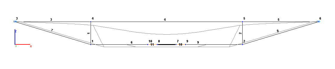
Design and deformed models
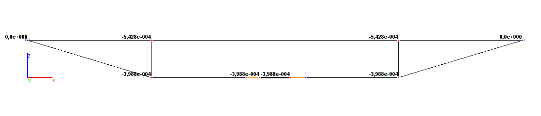
Values of vertical displacements Z (m)
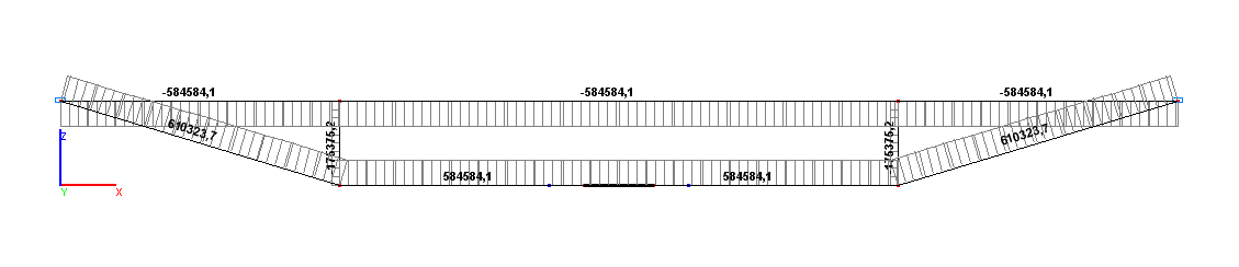
Values of longitudinal forces N (N)
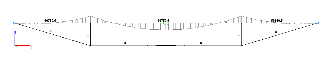
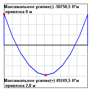
Values of bending moments M (N·m)
Comparison of solutions:
|
Parameter |
Theory |
SCAD |
Deviations, % |
|---|---|---|---|
|
Bending moment MH, N·m |
49249.5 |
49249.5 |
0.00 |
|
Longitudinal force NCE, N |
584584.0 |
584584.1 |
0.00 |
|
Vertical displacement ZD, m |
-5.428∙10-4 |
-5.428∙10-4 |
0.00 |