Two-Span Single-Storey Frame Subjected to a Constant Transverse Unit Force Moving Along the Girder Spans with a Small Speed. Plotting of Influence Lines of Internal Forces in the Frame Sections

Objective: Determination of the values of the bending moment in the section of the middle of the left girder span of a two-span single-storey frame depending on the position of a constant transverse unit force moving along the girder spans with a small speed.
Initial data file: Influence_Line.spr
Problem formulation: The constant transverse unit force P moves along the girder of the two-span single-storey frame with a small speed. The girder is rigidly connected with the middle and right edge columns, which have pinned supports, and the end of its left span is simply supported. Determine the values of the bending moment in the section of the middle of the left girder span of the frame M1-1 depending on the position of the transverse force and plot the influence line.
References: A. F. Smirnov, A. V. Aleksandrov, B. Ya. Lashchenikov, N. N. Shaposhnikov, Structural Mechanics. Bar Systems, Moscow, Stroyizdat, 1981, p. 352-356.
Initial data:
| l = 6.0 м | - length of the girders of the frame; |
| h = 6.0 м | - height of the columns of the frame; |
| EA = 1.0·106 kN | - axial stiffness of the structural members of the frame; |
| EI = 83.3333 kN·m2 | - bending stiffness of the structural members of the frame; |
| P = 1.0 kN | - value of the transverse unit force. |
Finite element model: Design model – plane frame, 24 elements of type 2. The spacing of the finite element mesh along the longitudinal axes of the structural elements (along the X1 axes of the local coordinate systems) is 1.0 m. The boundary conditions are provided by imposing constraints on the support nodes of the columns in the directions of the degrees of freedom X, Z and on the support node of the left girder span in the direction of the degree of freedom Z.
The problem is solved by the kinematic method:
- the elements of the middle of the left girder span are divided with the formation of a pair of duplicate nodes each one belonging to one of these adjacent elements;
- the displacements of the pair of duplicate nodes are merged for all degrees of freedom except for UY;
- unit concentrated opposite bending moments My = 1.0 kN∙m are applied to the nodes of the pair.
The result of the influence line of the bending moment in the section of the left frame span [nodes 26, 8] should be considered in the form of deformations according to the following formula: -Z/[UY26-UY8]/1000. It is necessary to divide the expression by 1000 if the dimension Z is given in mm.
Number of nodes in the design model – 26.
Results in SCAD
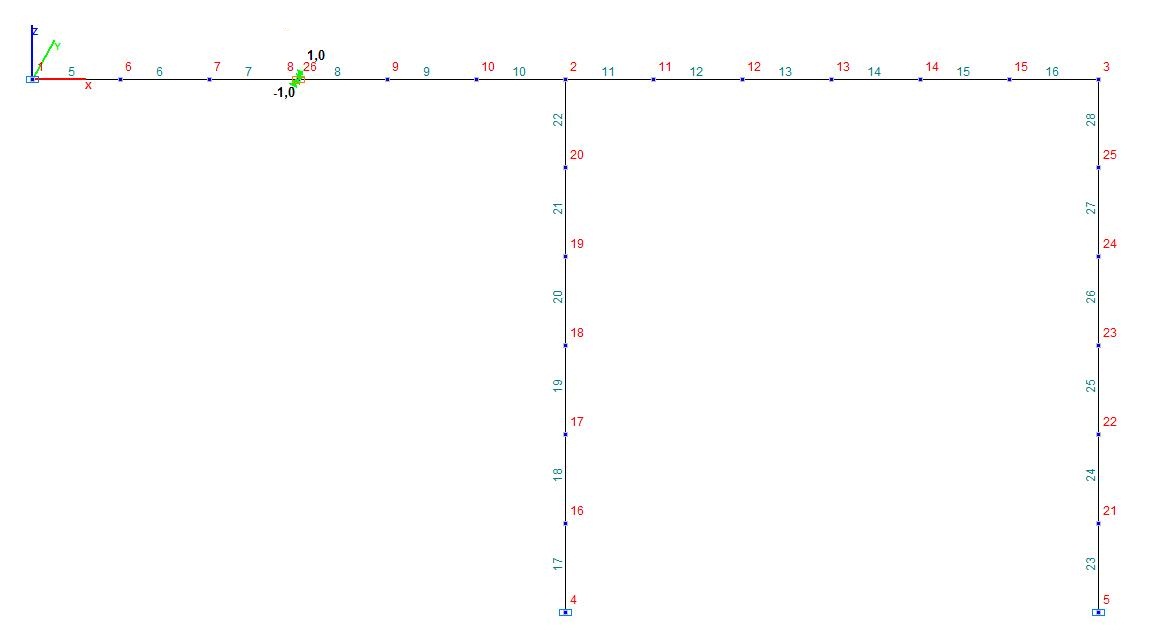
Design model
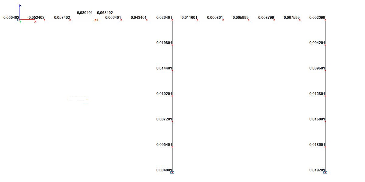
Values of rotation angles UY (rad)
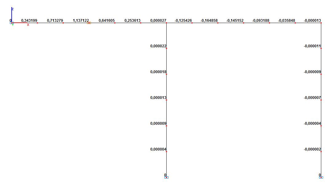
Values of the bending moment in the section of the middle of the left girder span of the frame M1-1 (kN∙m) depending on the position of the transverse force
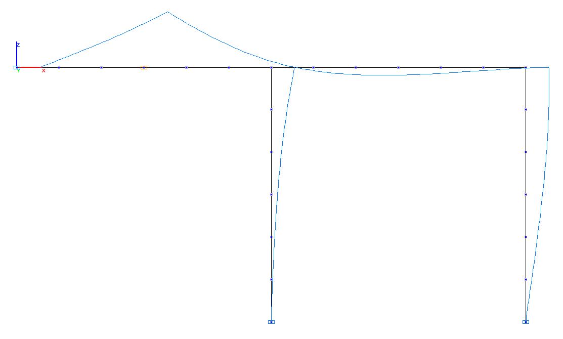
Influence lines of the bending moment in the section of the middle of the left girder span of the frame M1-1
Comparison of solutions:
Values of the bending moment in the section of the middle of the left girder span of the frame M1-1 (kN∙m) depending on the position of the transverse force
|
Position of the transverse force from the edge of the left span, m |
Theory |
SCAD |
Deviation, % |
|---|---|---|---|
|
0.00 |
0.000 |
0.000 |
0.00 |
|
1.00 |
0.343 |
0.343 |
0.00 |
|
2.00 |
0.714 |
0.713 |
0.14 |
|
3.00 |
1.137 |
1.137 |
0.00 |
|
4.00 |
0.641 |
0.642 |
0.16 |
|
5.00 |
0.254 |
0.254 |
0.00 |
|
6.00 |
0.000 |
0.000 |
0.00 |
|
7.00 |
-0.125 |
-0.125 |
0.00 |
|
8.00 |
-0.165 |
-0.165 |
0.00 |
|
9.00 |
-0.144 |
-0.145 |
0.69 |
|
10.00 |
-0.093 |
-0.093 |
0.00 |
|
11.00 |
-0.036 |
-0.036 |
0.00 |
|
12.00 |
0.000 |
0.000 |
0.00 |