Pure Bending of a Square Plate in the Plane Stress State Clamped on One Side and Simply Supported in the Center of the Opposite Side

Objective: Check of the equilibrium of the plate sections parallel to the support sides by the shear stresses.
Initial data files:
|
File name |
Description |
|---|---|
|
1 variant of the design model – support bar from elements of finite rigidity of type 2 |
|
|
2 variant of the design model – support bar from the rigid body element of type 100 |
Problem formulation: The square plate in the plane stress state clamped on one side and simply supported by a rigid bar on the opposite side is subjected to a pair of concentrated forces P, applied at the opposite ends of the bar and directed perpendicular to its axis. Check the equality of the values of the areas of shear stress diagrams τ for the plate sections parallel to the support sides and the values of the respective support reactions H.
References: Perelmuter A.V., Slivker V.I. Design models of structures and a possibility of their analysis. — Moscow: SCAD SOFT, 2011.
Initial data:
| E = 3.0·105 kPa | - elastic modulus; |
| ν = 0.25 | - Poisson’s ratio; |
| δ= 1.0 m | - thickness of the deep beam; |
| a = 16.0 m | - plate side; |
| P = 1000.0 kN | - concentrated force. |
Finite element model: Two variants of the design model are considered.
Variant 1:
Design model – plane frame, plate elements – 64 eight-node elements of type 30, bar elements – 16 elements of type 2 (EA = 3.0·1015 kN, EI = 3.0·1012 kN∙m2). The spacing of the finite element mesh in the directions parallel to the support sides is 1.0 m. Number of nodes in the design model – 225.
Variant 2:
Design model – plane frame, plate elements – 64 eight-node elements of type 30, bar elements – 1 element of type 100 (rigid body with a master node in the center of the simply supported side of the plate). The spacing of the finite element mesh in the directions parallel to the support sides is 1.0 m. Number of nodes in the design model – 225.
Results in SCAD

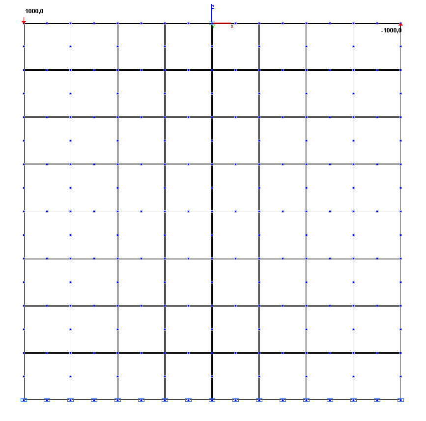
Design model. Variant 1
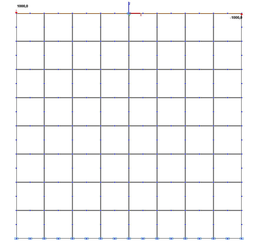
Design model. Variant 2
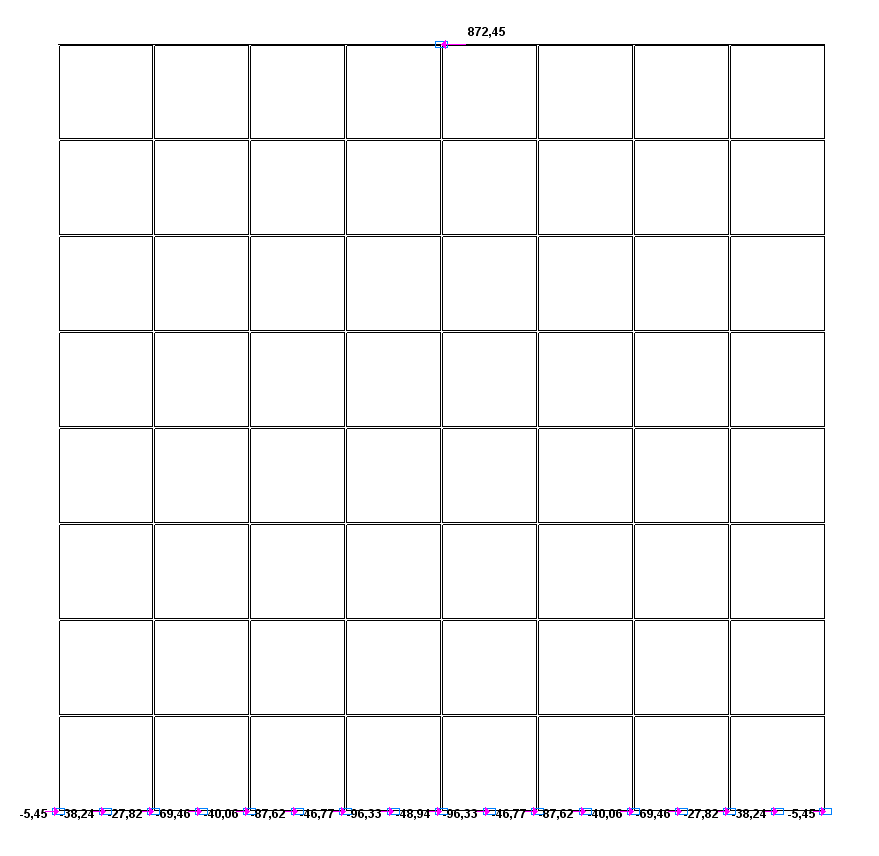
Values of support reactions H (kN) for the design model according to variant 1
Values of support reactions H (kN) for the design model according to variant 2
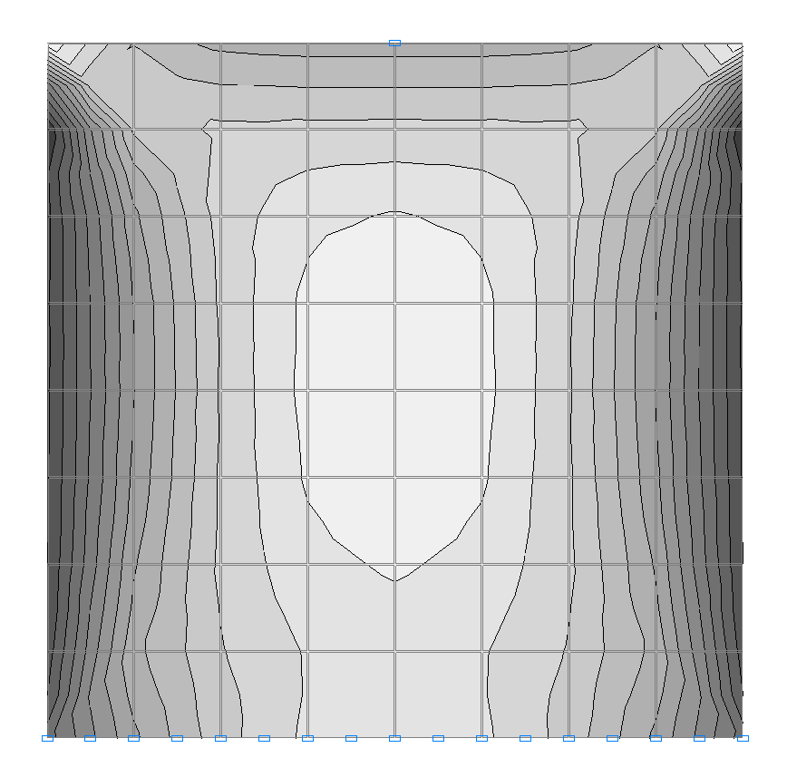
Isolines of stresses τ (kN/m2) for the design model according to variant 1
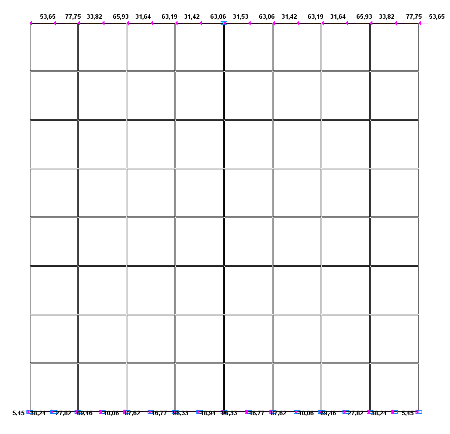
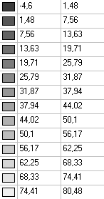
Values of stresses τ (kN/m2) for the design model according to variant 1
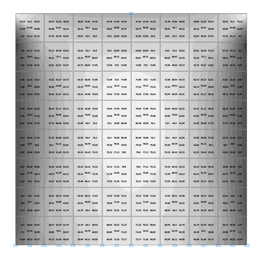
Isolines of stresses τ (kN/m2) for the design model according to variant 2
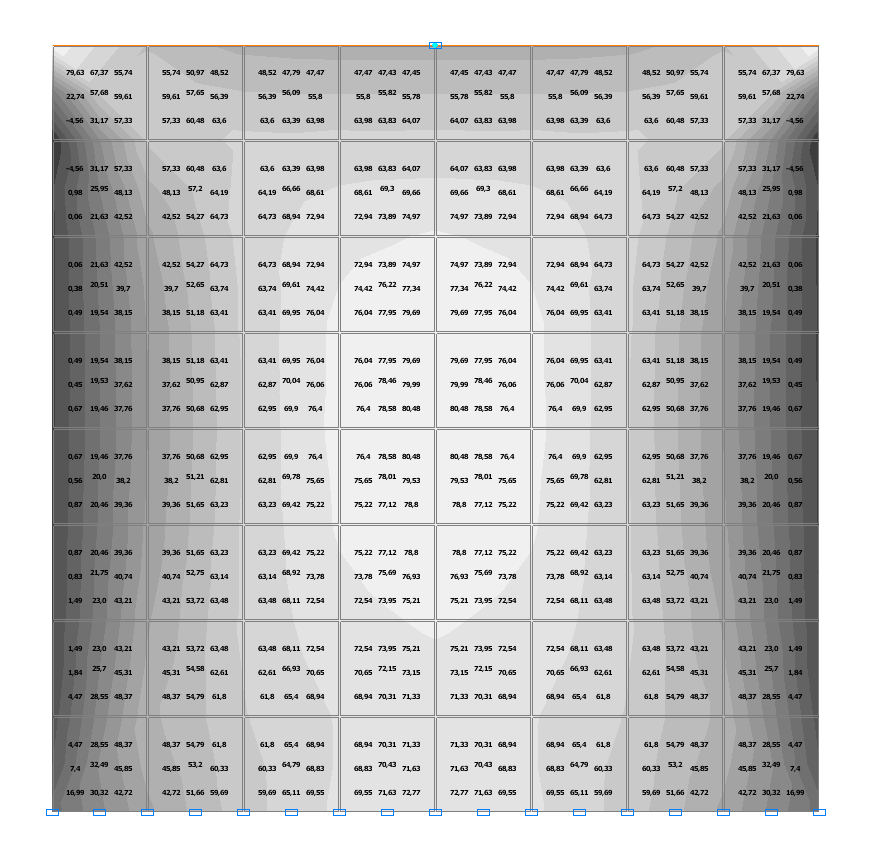
Values of stresses τ (kN/m2) for the design model according to variant 2
Comparison of solutions:
Comparison of the values of the areas of shear stress diagrams τ for the plate sections parallel to the support sides and located at the distance y from the simply supported side with the value of the support reaction H at the simply supported side.
|
Design model according to variant 1 H = 872.45 kN |
Design model according to variant 2 H = 872.45 kN |
||||
|---|---|---|---|---|---|
|
y, m |
|
Deviations, % |
y, m |
\[Q=\delta \cdot \int\limits_0^a {\tau \cdot } dx, кН\] |
Deviations, % |
|
0.0 |
857.71 |
1.69 |
0.0 |
857.67 |
1.69 |
|
2.0 |
867.07 |
0.62 |
2.0 |
867.06 |
0.62 |
|
4.0 |
872.87 |
0.05 |
4.0 |
872.88 |
0.05 |
|
6.0 |
872.60 |
0.02 |
6.0 |
872.61 |
0.02 |
|
8.0 |
872.59 |
0.02 |
8.0 |
872.59 |
0.02 |
|
10.0 |
872.61 |
0.02 |
10.0 |
872.62 |
0.02 |
|
12.0 |
872.70 |
0.03 |
12.0 |
872.71 |
0.03 |
|
14.0 |
872.10 |
0.04 |
14.0 |
872.11 |
0.04 |
|
16.0 |
871.11 |
0.15 |
16.0 |
871.12 |
0.15 |
 \[Q=\delta \cdot \int\limits_0^a {\tau \cdot } dx, кН\]