Bending of a Symmetric Wedge by a Concentrated Moment Applied to Its Vertex (Inglis Problem)

Objective: Determination of the stress state of a symmetric wedge of unit thickness in polar coordinates subjected to bending by a concentrated moment applied to its vertex.
Initial data file: 4_23.spr
Problem formulation: The moment M acting in the plane of the wedge X1OX2 is applied to the vertex of the wedge of unit thickness. Determine the stress tensor components in polar coordinates σrr, σθθ, σrθ at a radial distance r = 5.0 m from the vertex of the wedge.
References: S.P. Demidov, Theory of Elasticity. — Moscow: High school, 1979.
Initial data:
| E = 3.0·107 kPa | - elastic modulus; |
| μ = 0.2 | - Poisson’s ratio; |
| h = 1.0 m | - thickness of the wedge; |
| 2·α = 30º | - apex angle of the wedge; |
| R = 15.0 m | - radius of the fixed end of the wedge; |
| M = -25.0 kN | - concentrated moment bending the wedge. |
Finite element model: Design model – general type system, wedge elements – 280 eight-node elements of type 50. The spacing of the finite element mesh in the radial direction is 0.5 m, and in the tangential direction is 3º. The direction of the output of internal forces is radial tangential. Since in the case of a cylindrical surface of a small radius a the moment M at the vertex of the wedge cannot be represented as a resultant of stresses distributed according to the law of the analytical solution given below, the edge of the wedge is modeled by a rigid body with a master node at the vertex of the wedge and the slave nodes at the radial distance of a = 1.0 m from the vertex of the wedge (member type – 100). Since there are no forces distributed according to the law of the analytical solution at the fixed end of the wedge, in order to obtain an exact solution at the radial distance r = 5.0 m from the action of the moment M the radial distance to the fixed end is taken as R = 15.0 m. Number of nodes in the design model – 918.
Results in SCAD
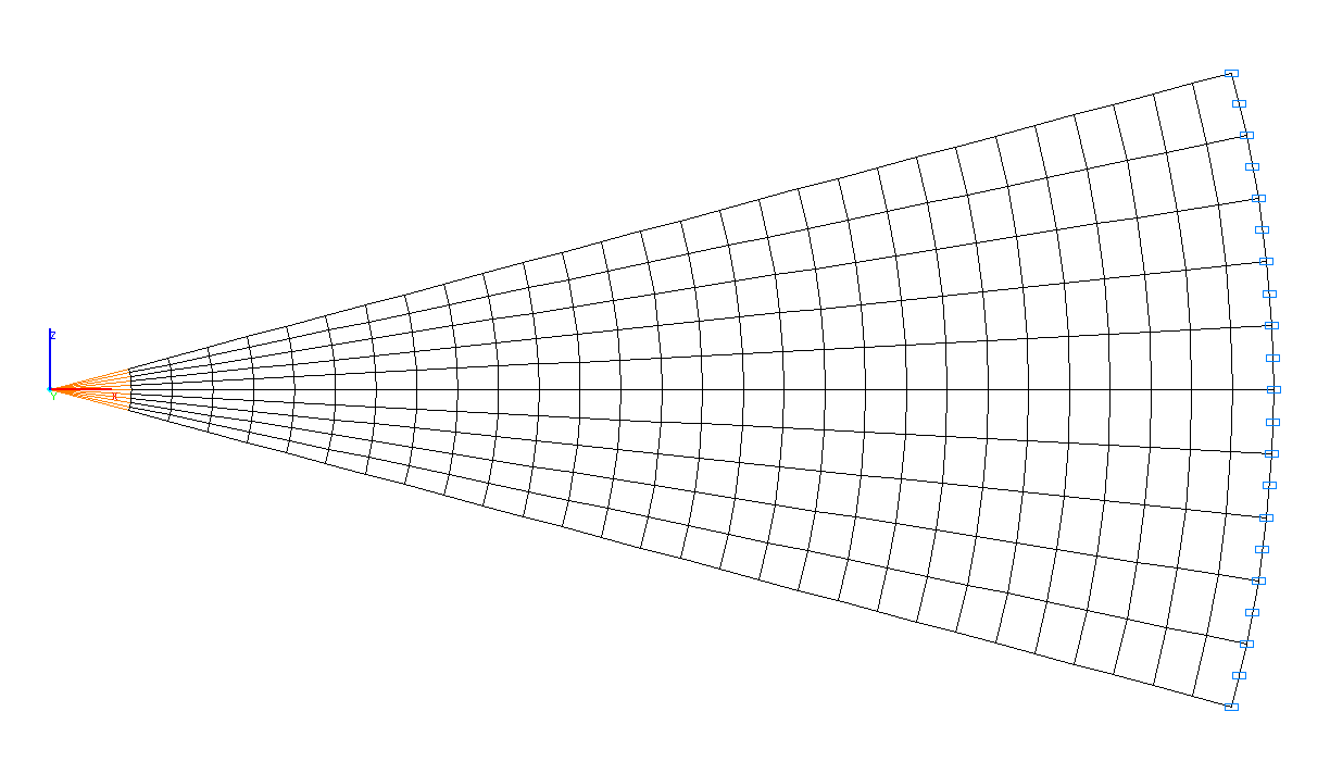
Design model
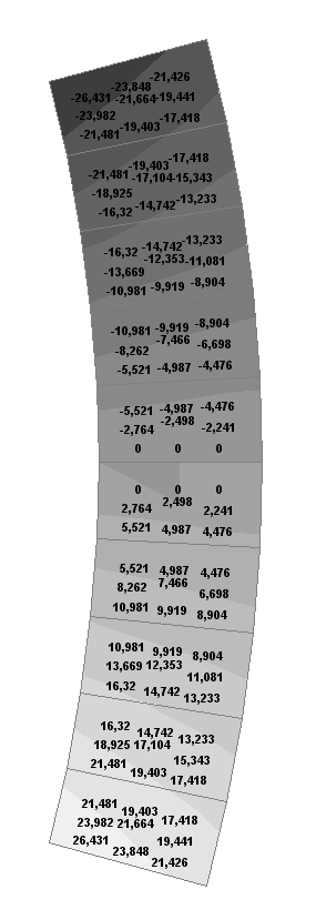
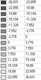
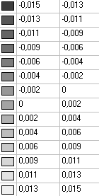
Values of stresses σrr (kN/m2) under the bending moment M
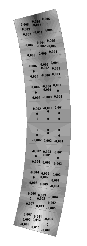
Values of stresses σθθ (kN/m2) under the bending moment M
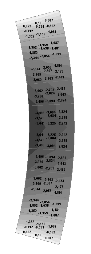
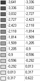
Values of stresses σrθ (kN/m2) under the bending moment M
Comparison of solutions:
Stress tensor components at a radial distance r = 5.0 m from the wedge top under the bending moment M.
|
Angle θ |
Stresses σrr (kN/m2) |
||
|---|---|---|---|
|
Theory |
SCAD |
Deviations, % |
|
|
-15º |
21.4822 |
21.4264 |
0.26 |
|
0º |
0.0000 |
0.0000 |
─ |
|
+15º |
-21.4822 |
-21.4264 |
0.26 |
|
Angle θ |
Stresses σθθ (kN/m2) |
||
|---|---|---|---|
|
Theory |
SCAD |
Deviations, % |
|
|
-15º |
0.0000 |
-0.0059 |
─ |
|
0º |
0.0000 |
0.0000 |
─ |
|
+15º |
0.0000 |
0.0059 |
─ |
|
Angle θ |
Stresses σrθ (kN/m2) |
||
|---|---|---|---|
|
Theory |
SCAD |
Deviations, % |
|
|
-15º |
0.0000 |
0.5071 |
─ |
|
0º |
-2.8781 |
-2.9418 |
2.21 |
|
+15º |
0.0000 |
0.5071 |
─ |
Notes: In the analytical solution the stresses σrr, σθθ, σrθ in the body of the wedge subjected to the bending moment M are determined according to the following formulas (S.P. Demidov, Theory of Elasticity. — Moscow: High school, 1979, p. 276):
\[ \sigma_{rr} =-\frac{2\cdot M\cdot \sin \left( {2\cdot \theta } \right)}{r^{2}\cdot \left( {2\cdot \alpha -tg\left( {2\cdot \alpha } \right)} \right)\cdot \cos \left( {2\cdot \alpha } \right)}; \quad \sigma_{\theta \theta } =0; \quad \sigma_{r\theta } =\frac{M\cdot \left( {\cos \left( {2\cdot \alpha } \right)-\cos \left( {2\cdot \theta } \right)} \right)}{r^{2}\cdot \left( {2\cdot \alpha -tg\left( {2\cdot \alpha } \right)} \right)\cdot \cos \left( {2\cdot \alpha } \right)}. \]