Plane Subjected to a Concentrated Moment and a Concentrated Force

Objective: Determination of the stress state of a plane of unit thickness in polar coordinates subjected to a concentrated moment and a concentrated force.
Initial data file: 4_26.spr
Problem formulation: The concentrated moment M and the concentrated force P1 acting along the Ox1 axis are applied in the origin of the plane of the unit thickness. Determine the stress tensor components in polar coordinates σrr, σθθ, σrθ at different radial distances r from the origin of the plane at the angle to the Ox1 axis θ = 0º.
References: S.P. Demidov, Theory of Elasticity. — Moscow: High school, 1979.
Initial data:
| E = 3.0·107 kPa | - elastic modulus; |
| ν = 0.2 | - Poisson’s ratio; |
| h = 1.0 m | - thickness of the plane; |
| R = 10.0 m | - radius bounding the area of the plane along the fixed edge; |
| M = 100.0 kN·m | - concentrated moment acting in the plane; |
| P1 = 100.0 kN | - concentrated force acting in the plane along the OX1 axis. |
| P2 = 0.0 kN | - concentrated force acting in the plane along the OX2 axis. |
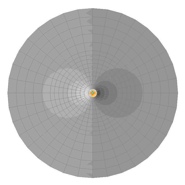
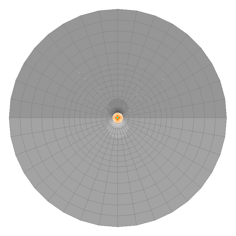
Finite element model: Design model – plane frame, plate elements – 972 eight-node elements of type 30. The spacing of the finite element mesh in the radial direction from r = 0.00 m to r = 0.50 m is 0.05 m, from r = 0.50 m to r = 1.00 m is 0.10 m, from r = 1.00 m to r = 5.00 m is 0.50 m, from r = 5.00 m to r = 10.00 m is 1.00 m, and in the tangential direction the spacing is 10º. The direction of the output of internal forces is radial tangential. A concentrated moment M and a concentrated force P1 in the vicinity of their application point on the cylindrical surface of a small radius a cannot be represented as a resultant of stresses distributed according to the laws of the analytical solution given below. Therefore, the area of the plane bounded by this cylindrical surface is modeled by a rigid body with a master node at the point of the application of concentrated forces and the slave nodes at the radial distance of a = 0.05 m from it (member type – 100). In order to exclude the effect of the boundary conditions on the accuracy of the solution, the radial distance to the fixed edge of the plane is taken as R = 10.0 m. Number of nodes in the design model – 2989.
Results in SCAD

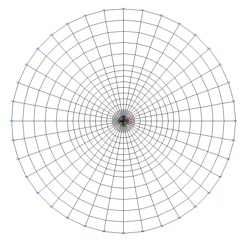
Design model
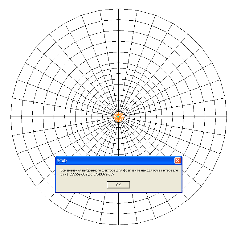
Values of stresses σrr (kN/m2) under the concentrated moment M
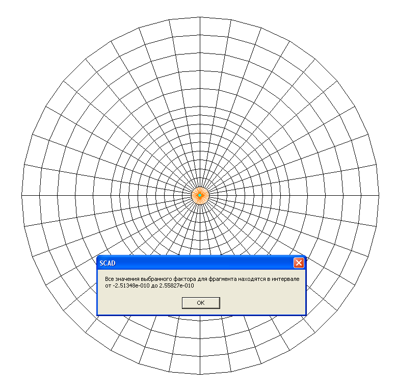
Values of stresses σθθ (kN/m2) under the concentrated moment M
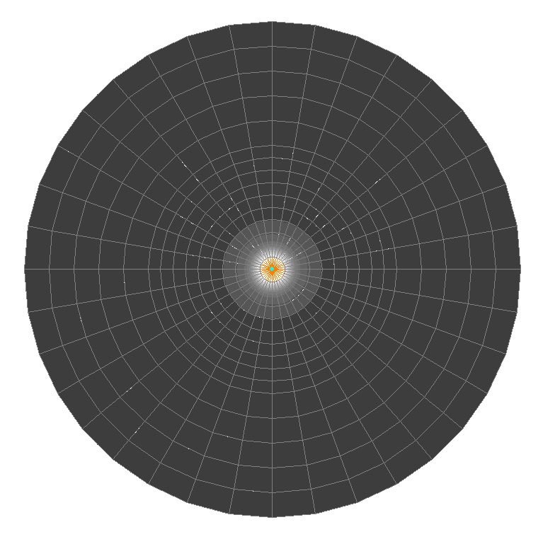
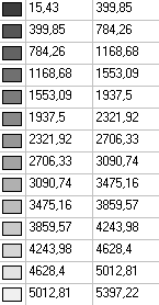
Values of stresses σrθ (kN/m2) under the concentrated moment M
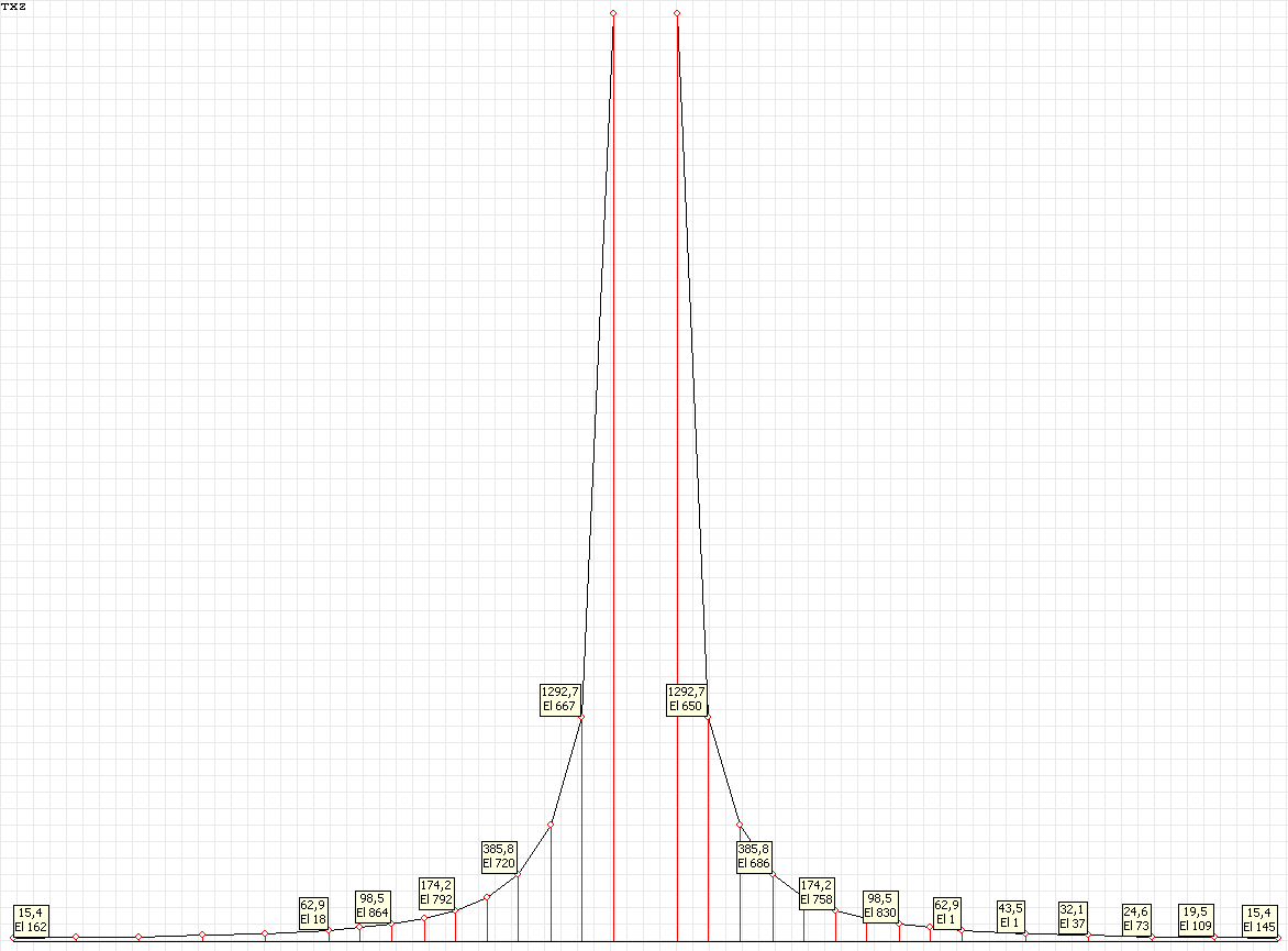
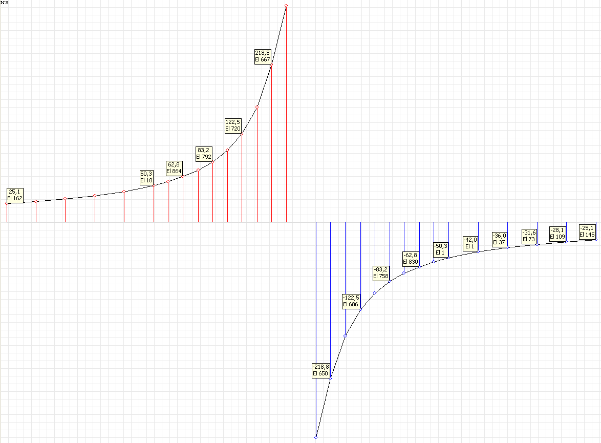
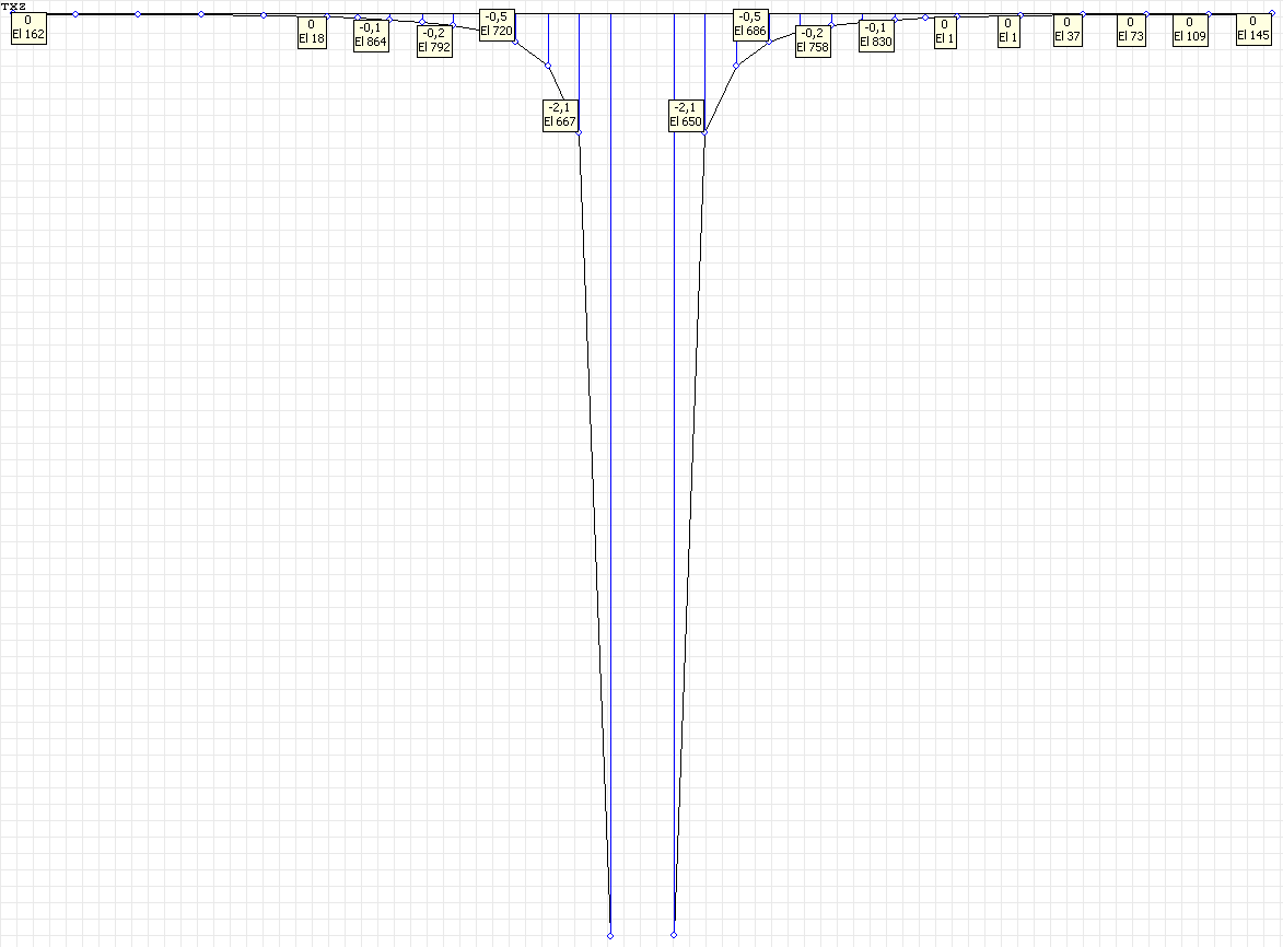
Stress diagram σrθ (kN/m2) under the concentrated moment M for the angle to the OX1 axis θ = 0º
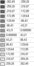
Values of stresses σrr (kN/m2) under the concentrated force P1
Stress diagram σrr (kN/m2) under the concentrated force P1 for the angle to the OX1 axis θ = 0º
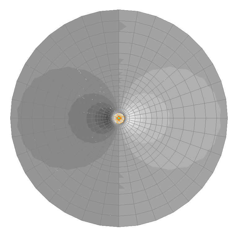
Values of stresses σθθ (kN/m2) under the concentrated force P1
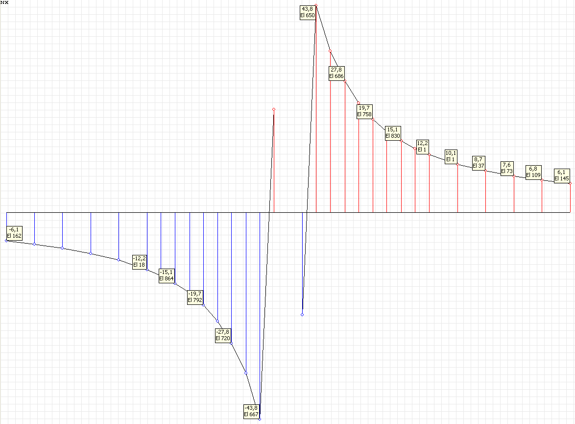
Stress diagram σθθ (kN/m2) under the concentrated force P1 for the angle to the OX1 axis θ = 0º
Values of stresses σrθ (kN/m2) under the concentrated force P1
Stress diagram σrθ (kN/m2) under the concentrated force P1 for the angle to the OX1 axis θ = 0º
Comparison of solutions:
Stress tensor components for the angle to the Ox1 axis θ = 0º under the concentrated moment M
|
Radius r (m) |
Stresses σrr (kN/m2) |
||
|---|---|---|---|
|
Theory |
SCAD |
Deviations, % |
|
|
0.2 |
0.00 |
0.00 |
─ |
|
0.3 |
0.00 |
0.00 |
─ |
|
0.4 |
0.00 |
0.00 |
─ |
|
0.5 |
0.00 |
0.00 |
─ |
|
1.0 |
0.00 |
0.00 |
─ |
|
1.5 |
0.00 |
0.00 |
─ |
|
2.0 |
0.00 |
0.00 |
─ |
|
2.5 |
0.00 |
0.00 |
─ |
|
3.0 |
0.00 |
0.00 |
─ |
|
Radius r (m) |
Stresses σθθ (kN/m2) |
||
|---|---|---|---|
|
Theory |
SCAD |
Deviations, % |
|
|
0.2 |
0.00 |
0.00 |
─ |
|
0.3 |
0.00 |
0.00 |
─ |
|
0.4 |
0.00 |
0.00 |
─ |
|
0.5 |
0.00 |
0.00 |
─ |
|
1.0 |
0.00 |
0.00 |
─ |
|
1.5 |
0.00 |
0.00 |
─ |
|
2.0 |
0.00 |
0.00 |
─ |
|
2.5 |
0.00 |
0.00 |
─ |
|
3.0 |
0.00 |
0.00 |
─ |
|
Radius r (m) |
Stresses σrθ (kN/m2) |
||
|---|---|---|---|
|
Theory |
SCAD |
Deviations, % |
|
|
0.2 |
397.89 |
385.79 |
3.04 |
|
0.3 |
176.84 |
174.22 |
1.48 |
|
0.4 |
99.47 |
98.49 |
0.99 |
|
0.5 |
63.66 |
62.93 |
1.15 |
|
1.0 |
15.92 |
15.43 |
3.08 |
|
1.5 |
7.07 |
6.67 |
5.65 |
|
2.0 |
3.98 |
3.86 |
3.02 |
|
2.5 |
2.55 |
2.50 |
1.96 |
|
3.0 |
1.77 |
1.74 |
1.69 |
Stress tensor components for the angle to the Ox1 axis Ox1 θ = 0º under the concentrated force P1.
|
Radius r (m) |
Stresses σrr (kN/m2) |
||
|---|---|---|---|
|
Theory |
SCAD |
Deviations, % |
|
|
0.2 |
-127.32 |
-122.67 |
3.65 |
|
0.3 |
-84.88 |
-83.26 |
1.91 |
|
0.4 |
-63.66 |
-62.84 |
1.29 |
|
0.5 |
-50.93 |
-50.36 |
1.12 |
|
1.0 |
-25.46 |
-25.08 |
1.49 |
|
1.5 |
-16.98 |
-16.65 |
1.94 |
|
2.0 |
-12.73 |
-12.61 |
0.94 |
|
2.5 |
-10.19 |
-10.15 |
0.39 |
|
3.0 |
-8.49 |
-8.50 |
0.12 |
|
Radius r (m) |
Stresses σθθ (kN/m2) |
||
|---|---|---|---|
|
Theory |
SCAD |
Deviations, % |
|
|
0.2 |
31.83 |
27.80 |
12.66 |
|
0.3 |
21.22 |
19.69 |
7.21 |
|
0.4 |
15.92 |
15.08 |
5.28 |
|
0.5 |
12.73 |
12.16 |
4.48 |
|
1.0 |
6.37 |
6.09 |
4.40 |
|
1.5 |
4.24 |
3.96 |
6.60 |
|
2.0 |
3.18 |
2.92 |
8.18 |
|
2.5 |
2.55 |
2.27 |
10.98 |
|
3.0 |
2.12 |
1.82 |
14.15 |
|
Radius r (m) |
Stresses σrθ (kN/m2) |
||
|---|---|---|---|
|
Theory |
SCAD |
Deviations, % |
|
|
0.2 |
0.00 |
0.00 |
─ |
|
0.3 |
0.00 |
0.00 |
─ |
|
0.4 |
0.00 |
0.00 |
─ |
|
0.5 |
0.00 |
0.00 |
─ |
|
1.0 |
0.00 |
0.00 |
─ |
|
1.5 |
0.00 |
0.00 |
─ |
|
2.0 |
0.00 |
0.00 |
─ |
|
2.5 |
0.00 |
0.00 |
─ |
|
3.0 |
0.00 |
0.00 |
─ |
Notes:
1. In the analytical solution the stresses σrr, σθθ, σrθ in the plane under the concentrated moment are determined according to the following formulas (S.P. Demidov, Theory of Elasticity. — Moscow: High school, 1979, p. 299):
\[ \sigma_{rr} =0; \quad \sigma_{\theta \theta } =0; \quad \sigma_{r\theta } =-\frac{M}{2\cdot \pi \cdot r^{2}}. \]
In the analytical solution the stresses σrr, σθθ, σrθ in the plane under the concentrated force are determined according to the following formulas (S.P. Demidov, Theory of Elasticity. — Moscow: High school, 1979, p. 300):
\[ \sigma_{rr} =-\frac{3+\nu }{4\cdot \pi \cdot r}\cdot \left( {P_{1} \cdot \cos \theta +P_{2} \cdot \sin \theta } \right); \] \[ \sigma_{\theta \theta } =\frac{1-\nu }{4\cdot \pi \cdot r}\cdot \left( {P_{1} \cdot \cos \theta +P_{2} \cdot \sin \theta } \right); \] \[ \sigma_{r\theta } =\frac{1-\nu }{4\cdot \pi \cdot r}\cdot \left( {P_{1} \cdot \sin \theta -P_{2} \cdot \cos \theta } \right). \]
2. It is impossible to perform an accurate modeling of the problem considered in the source in SCAD, because an infinite plane is considered, and the solution has a singularity. Therefore, the verification matrix contains deviations from the theoretical solution in the point located at the distance of 1,5 m from the origin.