Plane Hinged Bar System with Elements of Different Material Subjected to Temperature Variation


Objective: Determination of the stress state of a plane hinged bar system with elements of different material subjected to temperature variation.
Initial data file: T1_v11.3.spr
Problem formulation:
Three bars of the plane system are connected by hinges in the common node (O) and are simply supported in the opposite nodes (B, C, D). Support nodes are arranged on one horizontal straight line symmetrically with respect to the vertical axis (OC), the common node lies on the vertical axis. The vertical bar (OC) is made of steel, the inclined bars (OB, OD) are made of copper. The system is subjected to the temperature variation ∆t relative to the assembly temperature. Determine longitudinal forces N in each bar.
References: S.P. Timoshenko, Strength of Materials, Volume 1: Elementary Theory and Problems, Moscow, Nauka, 1965, p. 34.
Initial data:
| Es = 2.0·106 kgf/cm2 | - elastic modulus of steel; |
| Eс = 1.0·106 kgf/cm2 | - elastic modulus of copper; |
| αs = 1.25·10-5 1/ ºC | - linear thermal expansion coefficient of steel; |
| αc = 1.65·10-5 1/ ºC | - linear thermal expansion coefficient of copper; |
| l = 100.0 cm | - length of the vertical bar; |
| φ = 45 º | - angle between inclined and vertical bars; |
| As = 5.0·5.0 cm2 | - cross-sectional area of a vertical steel bar; |
| Ac = 5.0·5.0 cm2 | - cross-sectional area of an inclined copper bar; |
| Δt = 50 ºC | - temperature variation of the system. |
Finite element model: Design model – plane hinged bar system, 3 elements of type 1. Boundary conditions are provided by imposing constraints in the support nodes in the directions of the degrees of freedom X, Z. The effect of the temperature variation of the system ∆t relative to the assembly temperature is specified as uniform along the longitudinal axes of all bar elements. Number of nodes in the design model – 4.
Results in SCAD

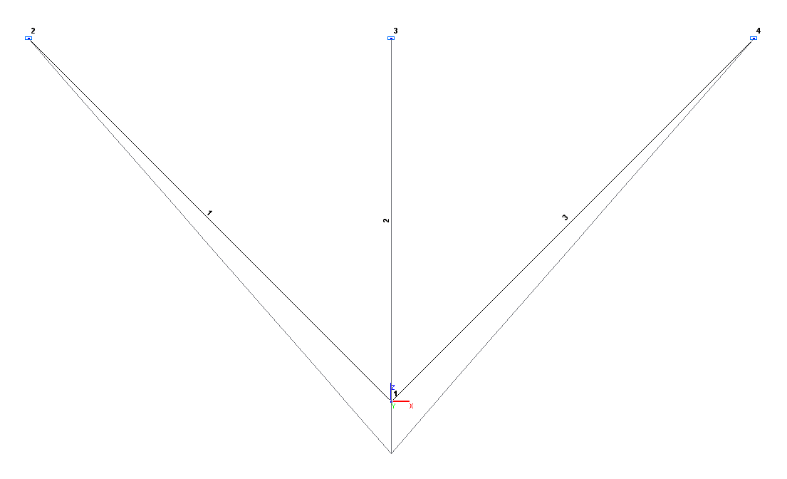 Design and deformed models
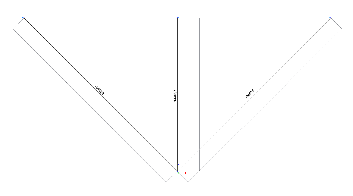 Longitudinal force diagram N (kgf)
Comparison of solutions:
|
Parameter |
Theory |
SCAD |
Deviations, % |
|---|---|---|---|
|
Longitudinal force N (bar OC), kgf |
13386.7 |
13386.7 |
0.00 |
|
Longitudinal force N (bars OB and OD), kgf |
-9465.8 |
-9465.8 |
0.00 |
Notes: In the analytical solution, the longitudinal forces N in the bars of the system are determined according to the following formulas:
\[ N_{OC} =\frac{\Delta t\cdot \left( {\frac{\alpha_{c} }{\cos^{2}\left( \phi \right)}-\alpha_{s} } \right)\cdot E_{s} \cdot A_{s} }{1+\frac{1}{2\cdot \cos^{3}\left( \phi \right)}\cdot \frac{E_{s} \cdot A_{s} }{E_{c} \cdot A_{c} }}; \]
\[N_{OB} =N_{OD} =-\frac{\Delta t\cdot \left( {\frac{\alpha_{c} }{\cos ^{2}\left( \phi \right)}-\alpha_{s} } \right)\cdot E_{s} \cdot A_{s} }{2\cdot \cos \left( \phi \right)+\frac{1}{\cos^{2}\left( \phi \right)}\cdot \frac{E_{s} \cdot A_{s} }{E_{c} \cdot A_{c} }}. \]