Unilateral Tension of a Plate with a Small Circular Hole (Kirsch Problem)

Objective: Determination of the stress state of a plate of considerable width and unit thickness with a small circular hole in polar coordinates subjected to unilateral uniform tension.
Initial data files:
|
File name |
Description |
|---|---|
|
1 variant of the design model – coarse FE mesh |
|
|
2 variant of the design model – fine FE mesh |
Problem formulation: The square plate of considerable width and unit thickness with a small circular hole of radius a is subjected to unilateral uniform tension by stresses σ in the direction of the x1 axis applied in its center. Determine the stress tensor components in polar coordinates σrr, σθθ, σrθ at different radial distances r from the origin at the angles to the x1 axis θ = 0º and θ = 90º.
References: S.P. Demidov, Theory of Elasticity. — Moscow: High school, 1979.
Initial data:
| E = 3.0·107 kPa | - elastic modulus; |
| μ = 0.2 | - Poisson’s ratio; |
| h = 1.0 м | - thickness of the plate; |
| a = 1.0 м | - radius of the hole; |
| 2·b = 20.0 м (60.0 м) | - width of the plate; |
| σ = 100.0 кН/м | - tensile stress in the direction of the x1 axis. |
Finite element model: Two variants of the design model are considered.
Variant 1:
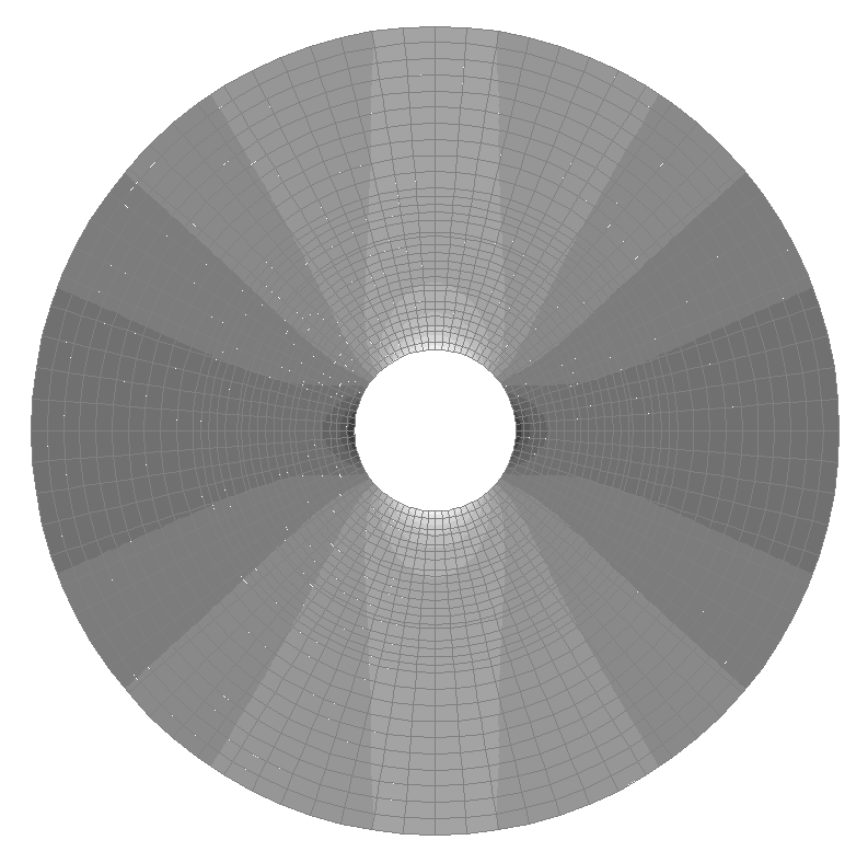
Design model – plane frame, width of the plate 2·b = 20.0 m, plate elements – 1088 eight-node elements of type 30 and 32 six-node elements of type 25. The spacing of the finite element mesh in the radial direction from r = 1.00 m to r = 2.00 m is 0.10 m, from r = 2.00 m to r = 10.00 m is 0.50 m and in the tangential direction the spacing is 9º. The direction of the output of internal forces is radial tangential. Number of nodes in the design model – 3409.
Variant 2:
Design model – plane frame, width of the plate 2·b = 60.0 m, plate elements – 5024 eight-node elements of type 30 and 40 six-node elements of type 25. The spacing of the finite element mesh in the radial direction from r = 1.00 m to r = 3.00 m is 0.10 m, from r = 3.00 m to r = 5.00 m is 0.20 m, from r = 5.00 m to r = 9.00 m is 0.40 m, from r = 9.00 m to r = 21.00 m is 0.80 m, from r = 21.00 m to r = 29.00 m is 1.60 m, and in the tangential direction the spacing is 4.5º. The direction of the output of internal forces is radial tangential. Number of nodes in the design model – 15312.
Results in SCAD

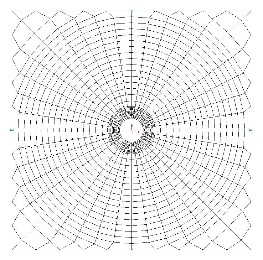
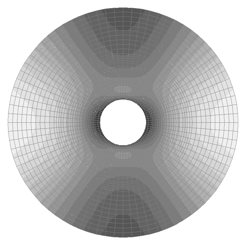
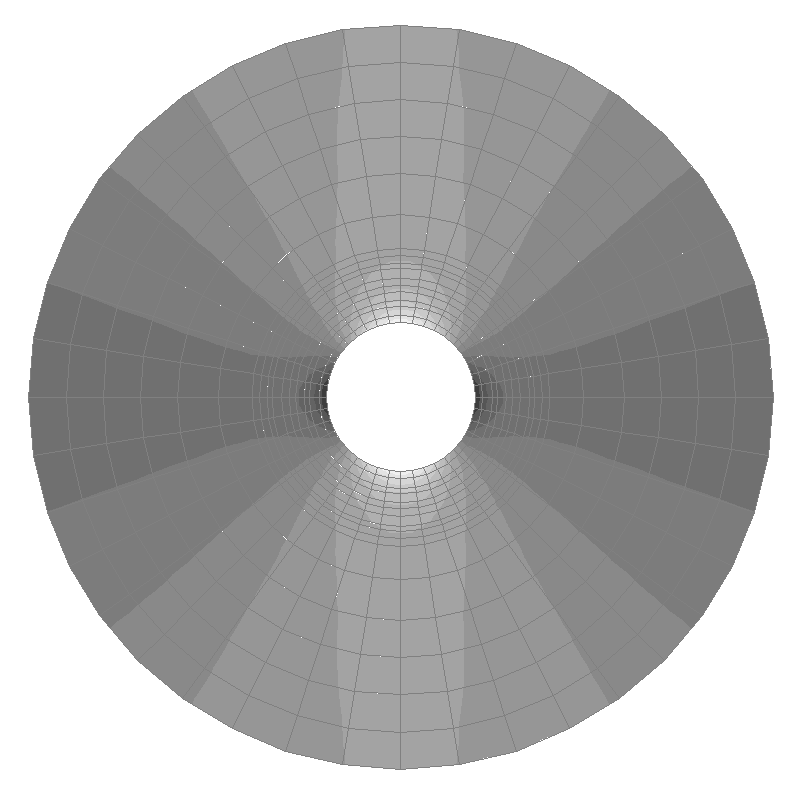
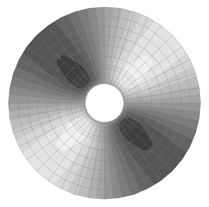
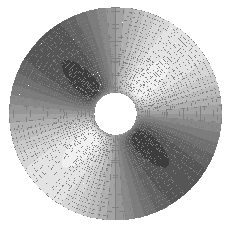
Design model. Variant 1
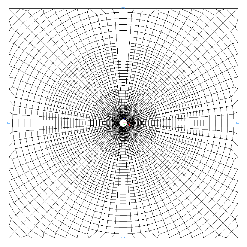
Design model. Variant 2
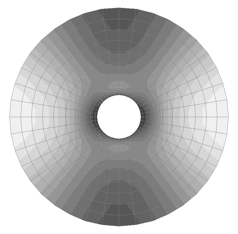
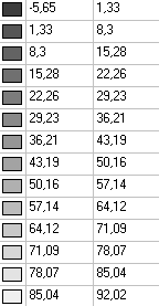
Values of stresses σrr (kN/m2) for the design model according to variant 1
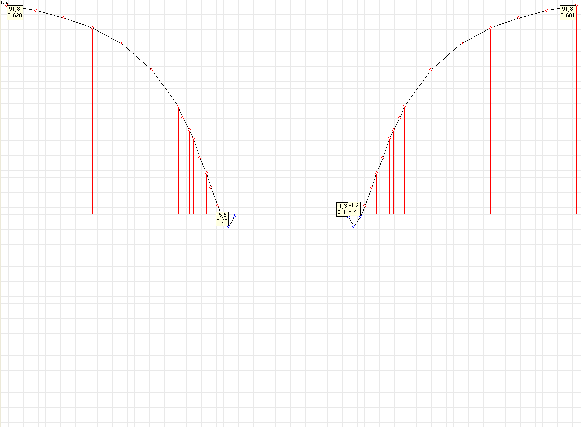
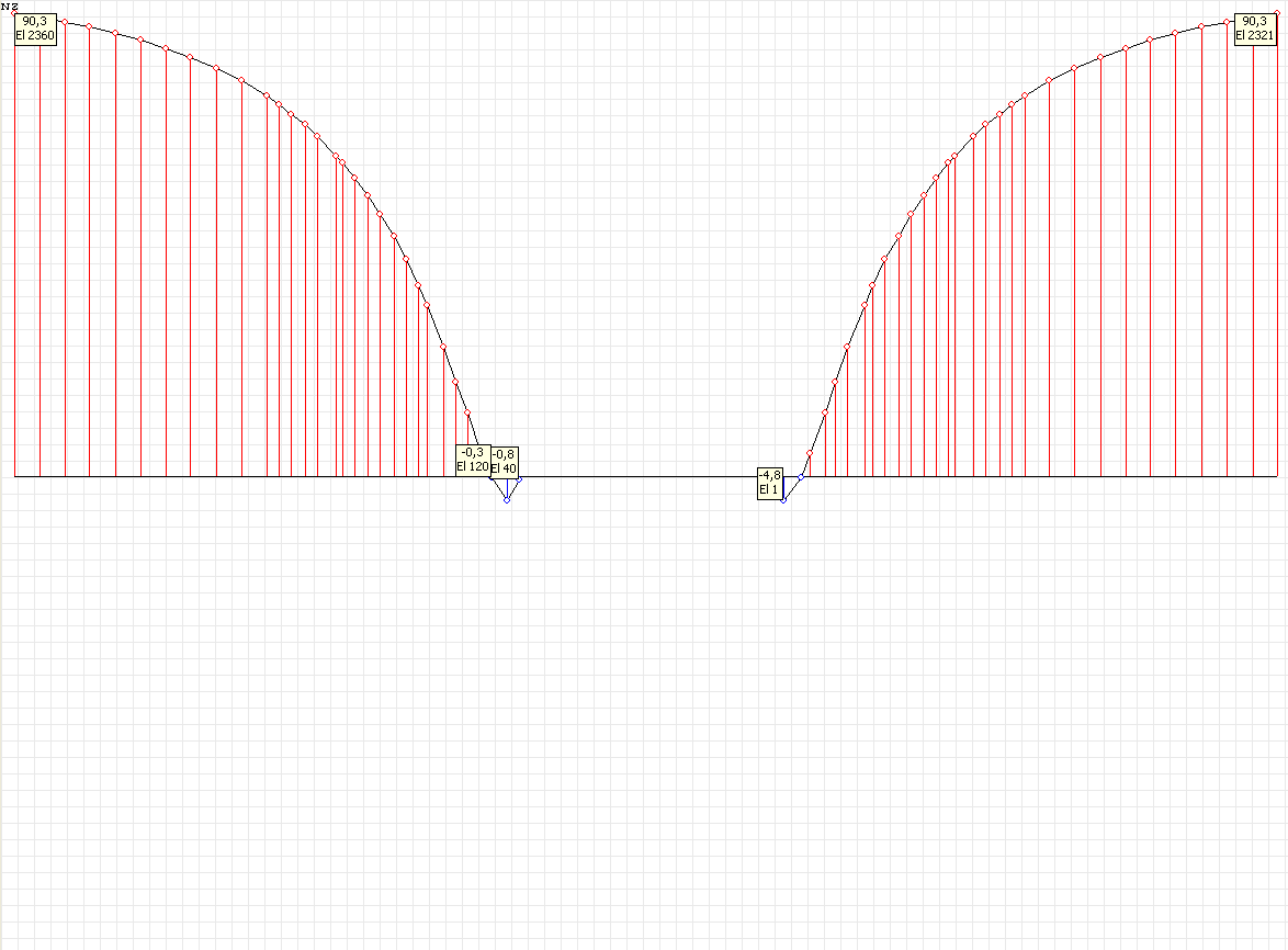
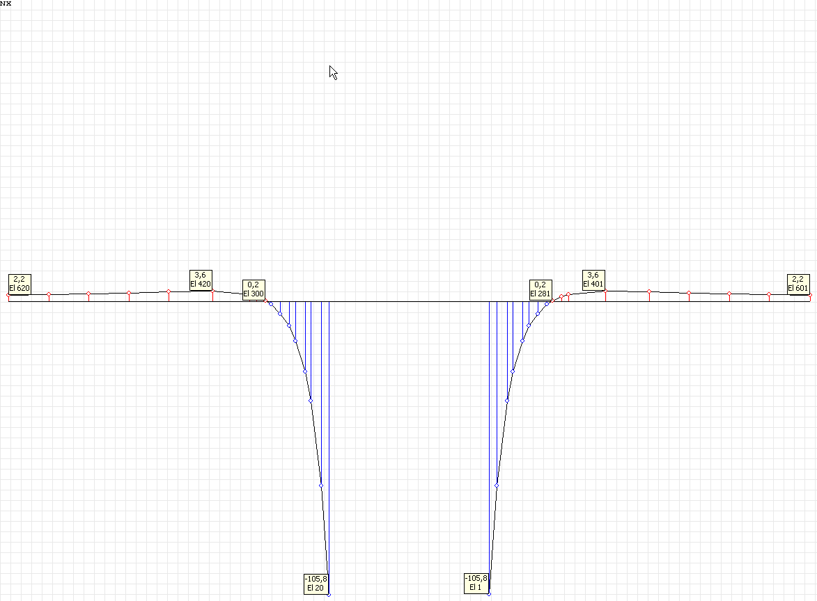
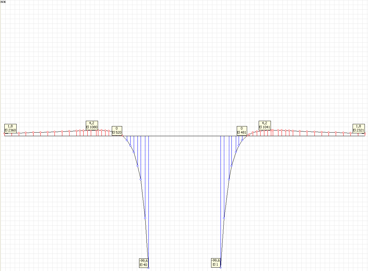
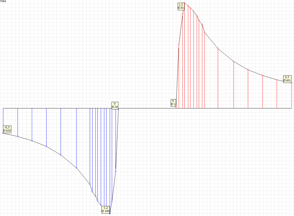
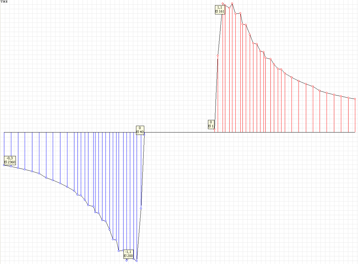
Stress diagram σrr (kN/m2) at the angle to the Ox1 axis θ = 0º for the design model according to variant 1
Stress diagram σrr (kN/m2) at the angle to the Ox1 axis θ = 90º for the design model according to variant 1
Values of stresses σrr (kN/m2) for the design model according to variant 2
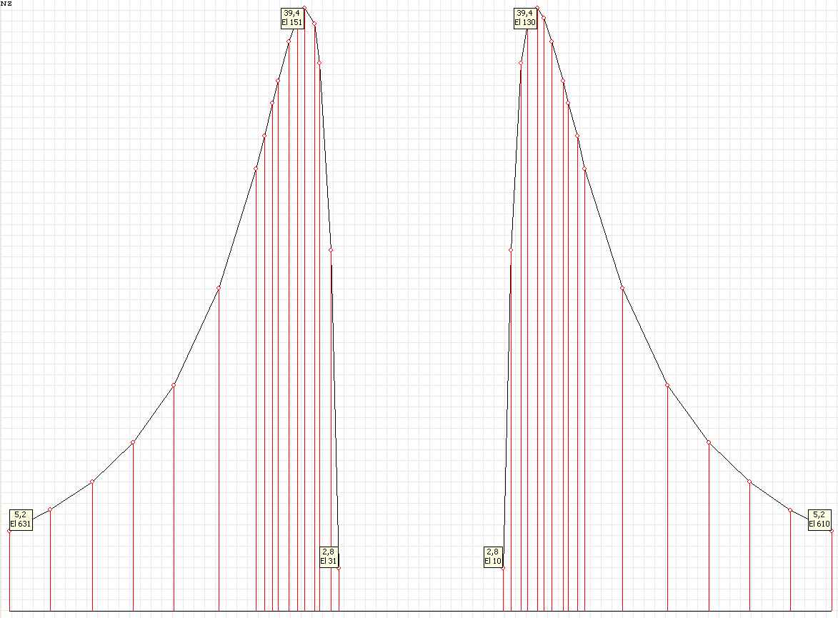
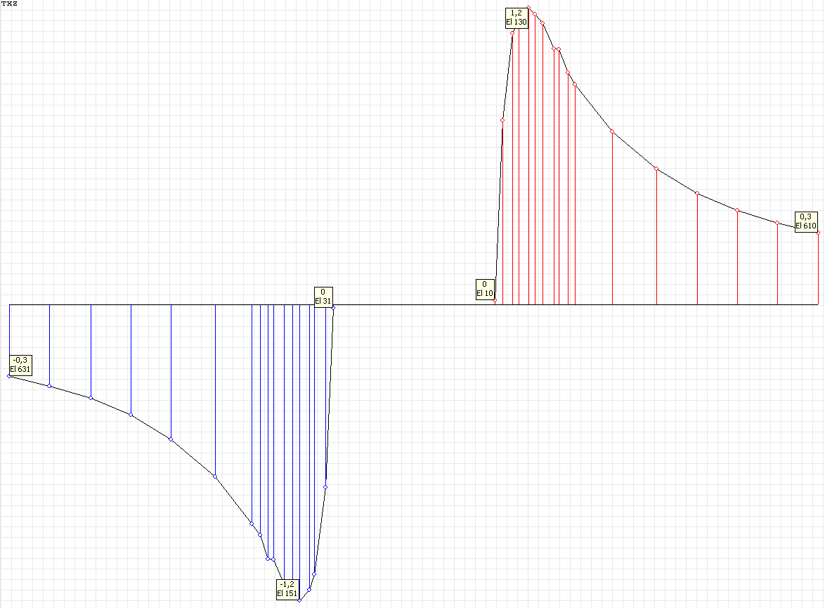
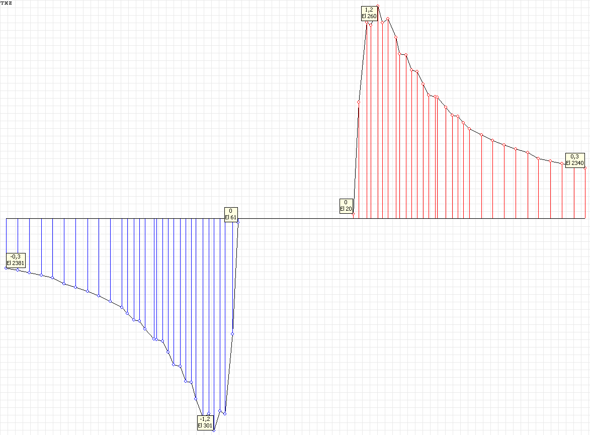
Stress diagram σrr (kN/m2) at the angle to the Ox1 axis θ = 0º for the design model according to variant 2
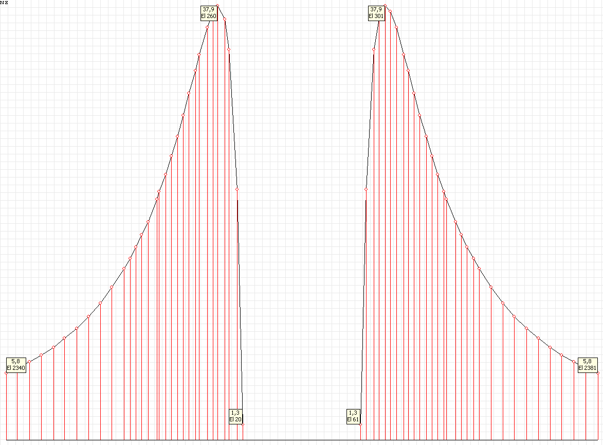
Stress diagram σrr (kN/m2) at the angle to the Ox1 axis θ = 90º for the design model according to variant 2
Values of stresses σθθ (kN/m2) for the design model according to variant 1
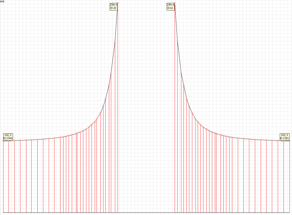
Stress diagram σθθ (kN/m2) at the angle to the Ox1 axis θ = 0º for the design model according to variant 1
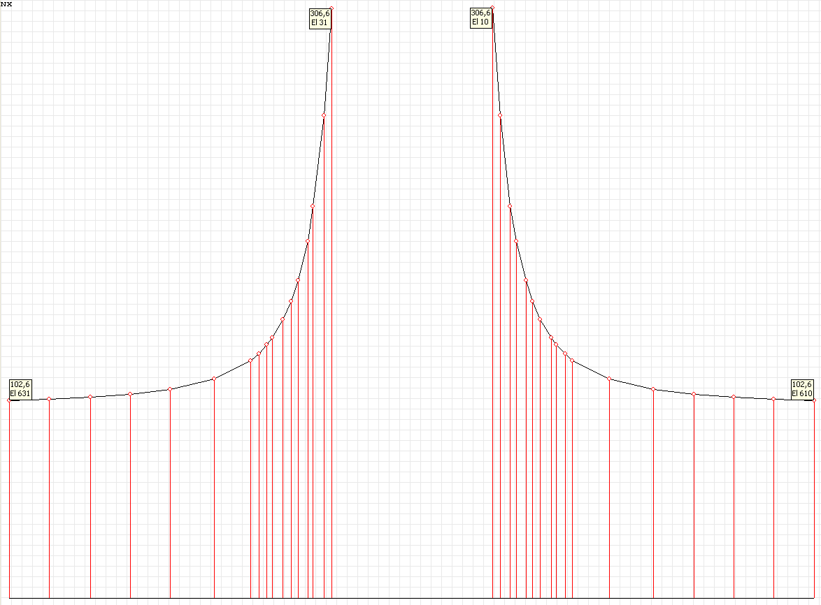
Stress diagram σθθ (kN/m2) at the angle to the Ox1 axis θ = 90º for the design model according to variant 1
Values of stresses σθθ (kN/m2) for the design model according to variant 2
Stress diagram σθθ (kN/m2) at the angle to the Ox1 axis θ = 0º for the design model according to variant 2
Stress diagram σθθ (kN/m2) at the angle to the Ox1 axis θ = 90º for the design model according to variant 2
Values of stresses σrθ (kN/m2) for the design model according to variant 1
Stress diagram σrθ (kN/m2) at the angle to the Ox1 axis θ = 0º for the design model according to variant 1

Stress diagram σrθ (kN/m2) at the angle to the Ox1 axis θ = 90º for the design model according to variant 1
Values of stresses σrθ (kN/m2) for the design model according to variant 2
Stress diagram σrθ (kN/m2) at the angle to the Ox1 axis θ = 0º for the design model according to variant 2
Stress diagram σrθ (kN/m2) at the angle to the Ox1 axis θ = 90º for the design model according to variant 2
Comparison of solutions:
Stress tensor components in polar coordinates σrr, σθθ, σrθ.
|
Solution |
Stresses σrr (kN/m2) |
Stresses σθθ (kN/m2) |
|||||||
|---|---|---|---|---|---|---|---|---|---|
|
θ = 0º |
θ = 90º |
θ = 0º |
θ = 90º |
||||||
|
r = 1.000 m |
r = (√6/5)·a = 1.095 m |
r = (√3/2)·a = 1.225 m |
r = 1.000 m |
r = (√2)·a = 1.414 m |
r = 1.000 m |
r = (√3)·a = 1.732 m |
r = (√6)·a = 2.449 m |
r = 1.000 m |
|
|
Theory |
0.00 |
-σ/24 = -4.17 |
0.00 |
0.00 |
3·σ/8 = 37.50 |
-σ = -100.00 |
0.00 |
σ/24 = 4.17 |
3·σ = 300.00 |
|
SCAD, DM var.1 |
-1.32 |
-5.65 |
-1.26 |
2.77 |
39.43 |
-100.63 |
-1.18 |
3.56 |
307.46 |
|
Deviations, % |
─ |
─ |
─ |
─ |
5.15 |
0.63 |
─ |
─ |
2.49 |
|
SCAD, DM var.2 |
-0.76 |
-4.78 |
-0.36 |
1.31 |
37.94 |
-100.05 |
-0.04 |
4.16 |
299.85 |
|
Deviations, % |
─ |
─ |
─ |
─ |
1.17 |
0.05 |
─ |
─ |
0.05 |
Notes: In the analytical solution the stresses σrr, σθθ, σrθ in the plate with a small circular hole subjected to unilateral uniform tension are determined according to the following formulas (S.P. Demidov, Theory of Elasticity. — Moscow: High school, 1979, p. 302):
\[ \sigma_{rr} =\frac{\sigma }{2}\cdot \left( {1-\frac{a^{2}}{r^{2}}} \right)+\frac{\sigma }{2}\cdot \left( {1-4\cdot \frac{a^{2}}{r^{2}}+3\cdot \frac{a^{4}}{r^{4}}} \right)\cdot \cos \left( {2\cdot \theta } \right); \] \[ \sigma_{\theta \theta } =\frac{\sigma }{2}\cdot \left( {1+\frac{a^{2}}{r^{2}}} \right)-\frac{\sigma }{2}\cdot \left( {1+3\cdot \frac{a^{4}}{r^{4}}} \right)\cdot \cos \left( {2\cdot \theta } \right); \] \[ \sigma_{r\theta } =-\frac{\sigma }{2}\cdot \left( {1+2\cdot \frac{a^{2}}{r^{2}}-3\cdot \frac{a^{4}}{r^{4}}} \right)\cdot \sin \left( {2\cdot \theta } \right). \]