Rectangular Plate Simply Supported along the Perimeter Subjected to a Uniformly Distributed Transverse Load

Objective: Determination of the stress-strain state of a rectangular plate simply supported along the perimeter and subjected to a uniformly distributed transverse load.
Initial data files:
|
File name |
Description |
|---|---|
|
Design model with the ratios of the sides of the plate b/a = 1.0 |
|
|
Design model with the ratios of the sides of the plate b/a = 2.0 |
|
|
Design model with the ratios of the sides of the plate b/a = 5.0 |
Problem formulation: The rectangular plate simply supported along the perimeter is subjected to the transverse load uniformly distributed over its area p. Determine the transverse displacement Z and bending moments Mx, My in the center of the plate for different ratios of its sides b/a.
References: S. Timoshenko, S. Woinowski, Theorie des plaques et des coques, Paris, Librairie Polytechnique Beranger, 1961.
Initial data:
| E = 1.0·107 Pa | - elastic modulus; |
| ν = 0.3 | - Poisson’s ratio; |
| h = 0.01 m | - thickness of the plate; |
| a = 1.0 m | - short side of the plate (along the X axis of the global coordinate system); |
| b = 1.0 m, 2.0 m, 5.0 m | - long side of the plate (along the Y axis of the global coordinate system); |
| p = 1.0 N/m2 | - value of the uniformly distributed transverse load. |
Finite element model: Three design models are considered.
Design model 1 (b/a = 1.0) – grade beam / plate, shell elements – 100 plate elements of type 20. Boundary conditions are provided by imposing constraints in the directions of the degrees of freedom Z, UY for the edges parallel to the X axis of the global coordinate system, and Z, UX for the edges parallel to the Y axis of the global coordinate system. Number of nodes in the design model – 121.
Design model 2 (b/a = 2.0) – grade beam / plate, shell elements – 200 plate elements of type 20. Boundary conditions are provided by imposing constraints in the directions of the degrees of freedom Z, UY for the edges parallel to the X axis of the global coordinate system, and Z, UX for the edges parallel to the Y axis of the global coordinate system. Number of nodes in the design model – 231.
Design model 3 (b/a = 5.0) – grade beam / plate, shell elements – 500 plate elements of type 20. Boundary conditions are provided by imposing constraints in the directions of the degrees of freedom Z, UY for the edges parallel to the X axis of the global coordinate system, and Z, UX for the edges parallel to the Y axis of the global coordinate system. Number of nodes in the design model – 561.
Results in SCAD

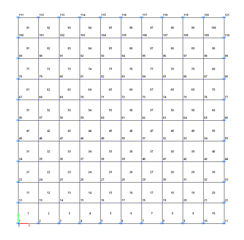
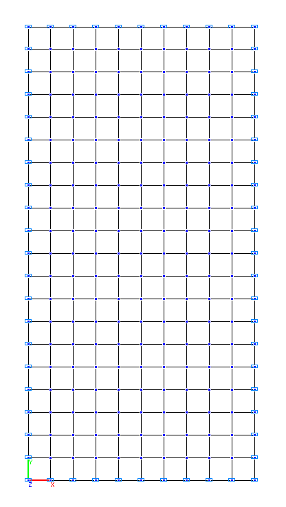
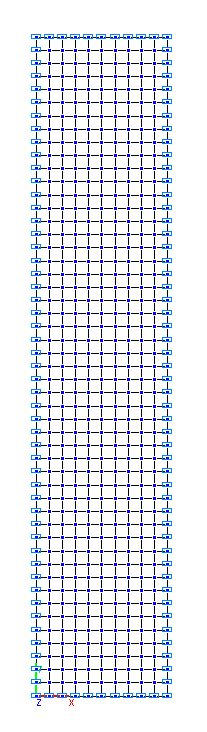
Design models 1, 2, 3
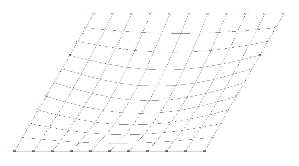
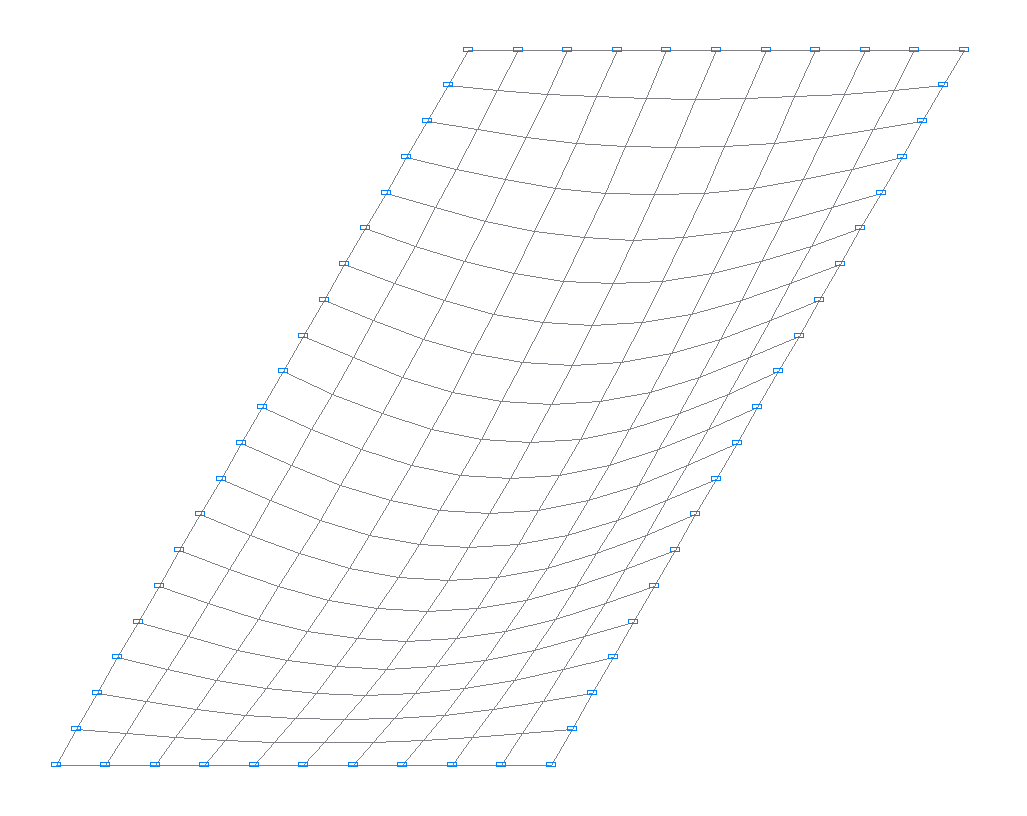
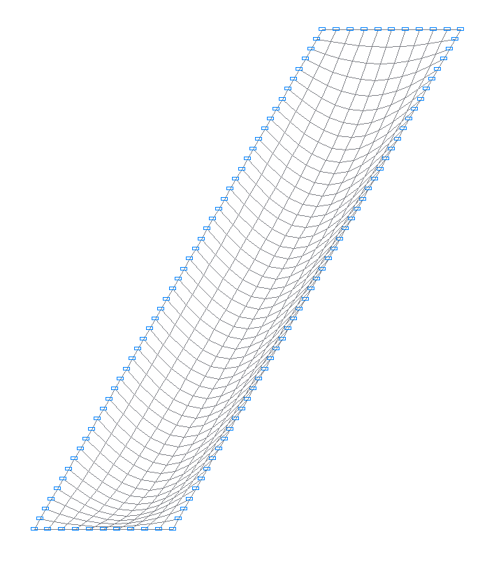
Deformed models 1, 2, 3
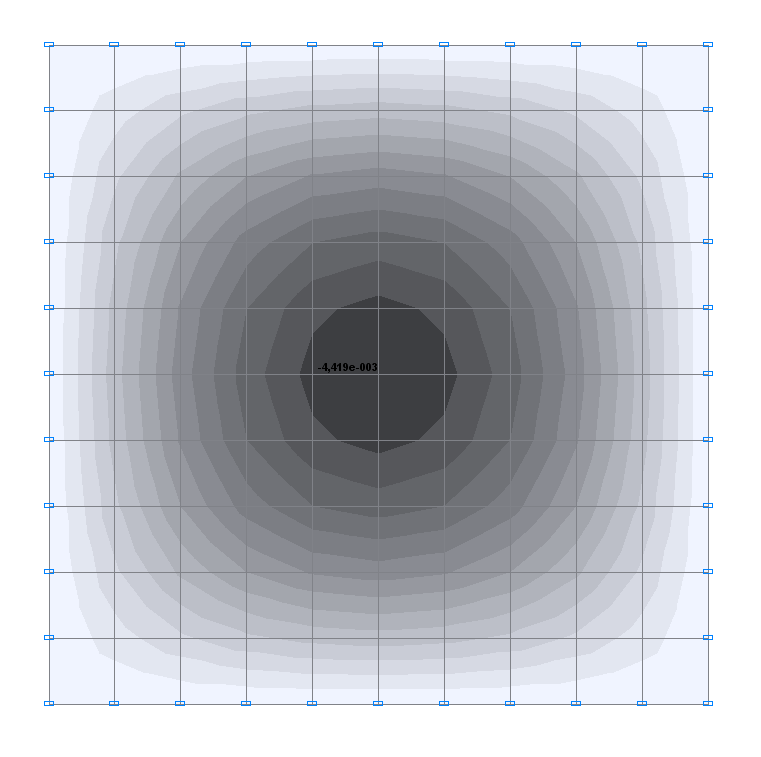
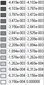
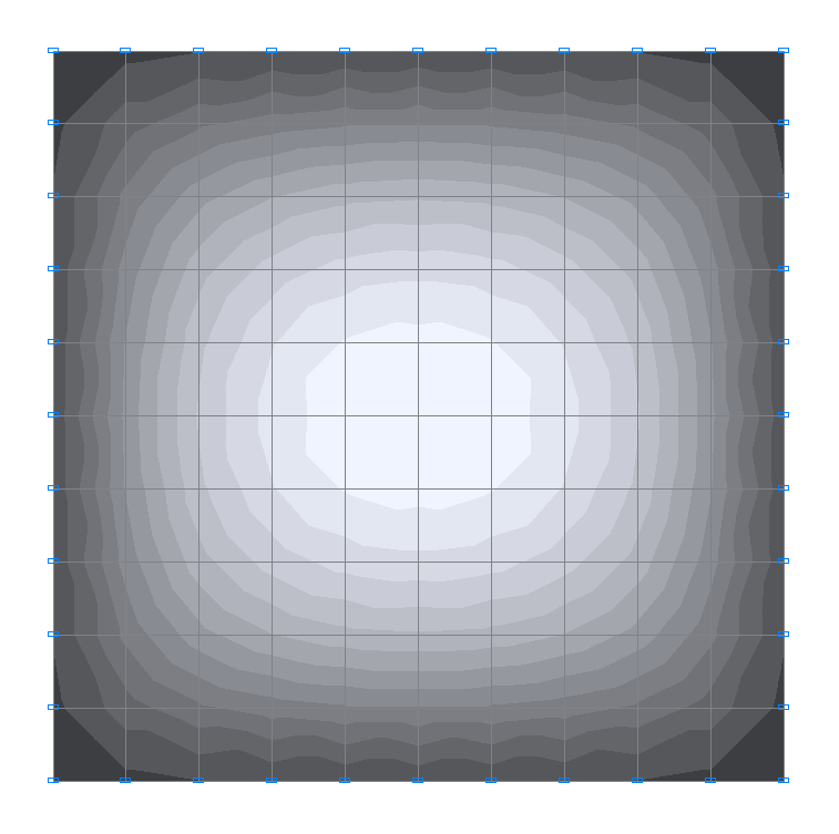
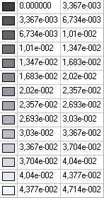
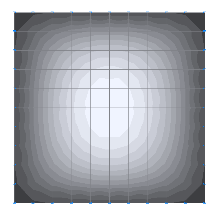
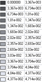
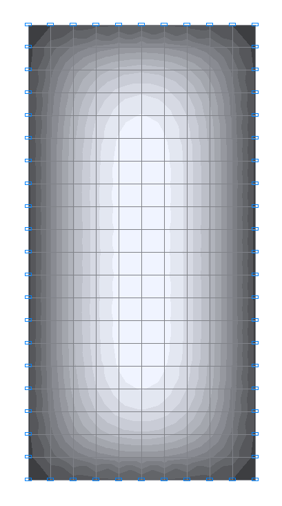
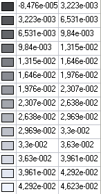
Values of transverse displacements Z (m) for the design model 1
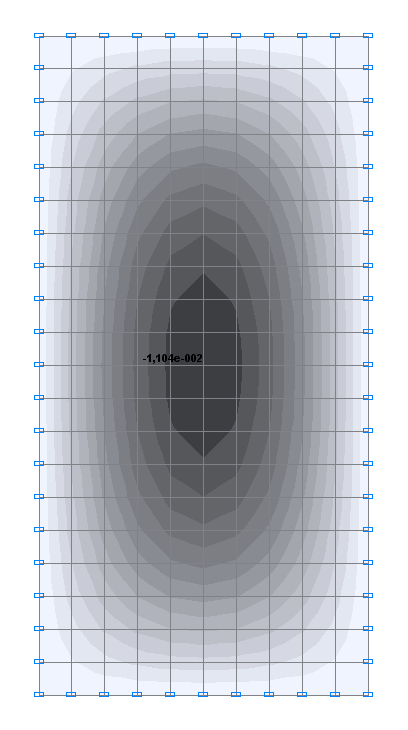
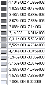
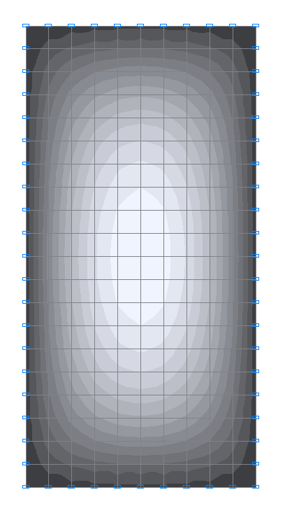
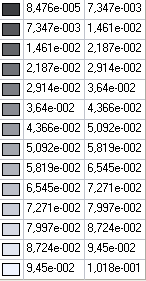
Values of transverse displacements Z (m) for the design model 2
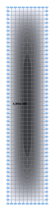
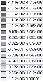
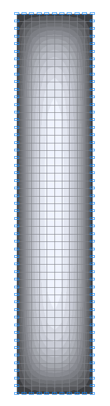
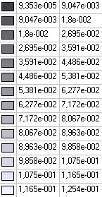
Values of transverse displacements Z (m) for the design model 3
Values of bending moments Mx (N·m/m) for the design model 1
Values of bending moments Mx (N·m/m) for the design model 2
Values of bending moments Mx (N·m/m) for the design model 3
Values of bending moments My (N·m/m) for the design model 1
Values of bending moments My (N·m/m) for the design model 2
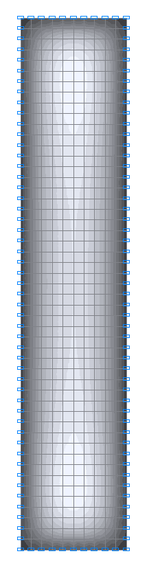
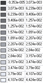
Values of bending moments My (N·m/m) for the design model 3
Comparison of solutions:
Design model 1 (b/a = 1.0)
|
Parameter |
Theory |
SCAD |
Deviation, % |
|---|---|---|---|
|
Transverse displacement Z in the center of the plate, m |
-4.436∙10-3 |
-4.419∙10-3 |
0.38 |
|
Bending moments Mx in the center of the plate, N·m/m |
4.789∙10-2 |
4.714∙10-2 |
1.57 |
|
Bending moments My in the center of the plate, N·m/m |
4.789∙10-2 |
4.714∙10-2 |
1.57 |
Design model 2 (b/a = 2.0)
|
Parameter |
Theory |
SCAD |
Deviation, % |
|---|---|---|---|
|
Transverse displacement Z in the center of the plate, m |
-1.106∙10-2 |
-1.104∙10-2 |
0.18 |
|
Bending moments Mx in the center of the plate, N·m/m |
1.017∙10-2 |
1.018∙10-2 |
0.10 |
|
Bending moments My in the center of the plate, N·m/m |
4.635∙10-2 |
4.607∙10-2 |
0.60 |
Design model 3 (b/a = 5.0)
|
Parameter |
Theory |
SCAD |
Deviation, % |
|---|---|---|---|
|
Transverse displacement Z in the center of the plate, m |
-1.416∙10-2 |
-1.416∙10-2 |
0.00 |
|
Bending moments Mx in the center of the plate, N·m/m |
1.246∙10-1 |
1.254∙10-1 |
0.64 |
|
Bending moments My in the center of the plate, N·m/m |
3.774∙10-2 |
3.798∙10-2 |
0.64 |
Notes: In the analytical solution the transverse displacement Z and bending moments Mx, My in the center of the plate for different ratios of its sides b/a can be determined according to the following formulas:
\[ Z=\alpha \cdot \frac{p\cdot a^{4}}{D}; \quad M_{x} =\beta \cdot p\cdot a^{2}; \quad M_{y} =\beta_{1} \cdot p\cdot a^{2}, \quad where: \] \[ at \quad \frac{a}{b}=1.0 \quad \alpha =0.004062, \quad \beta =0.047886, \quad \beta_{1}=0.047886, \] \[ at \quad \frac{a}{b}=2.0 \quad \alpha =0.010129, \quad \beta =0.101683, \quad \beta_{1}=0.046350, \] \[ at \quad \frac{a}{b}=5.0 \quad \alpha =0.012971, \quad \beta =0.124624, \quad \beta_{1}=0.037744,\] \[ D=\frac{E\cdot h^{3}}{12\cdot \left( {1-\mu^{2}} \right)}. \]